How LoRaWAN Works in IoT Systems
The Internet of Things connects sensors, controllers, gateways, software, and cloud services so that physical conditions can be measured, analysed, and acted upon.
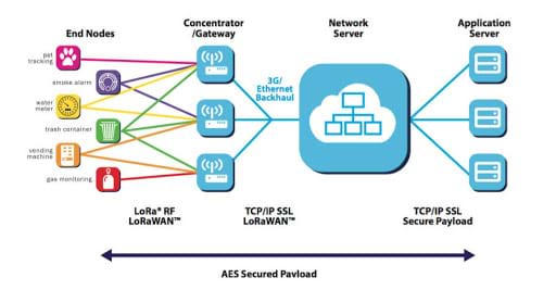
LoRaWAN, or Long Range Wide Area Network, is a low-power wide-area networking protocol designed for IoT deployments. End-devices exchange LoRa radio packets with one or more gateways. Each gateway then forwards those packets to a network server through a standard IP connection such as Ethernet, Wi-Fi, or cellular data.
The gateway does not normally interpret the sensor payload. It relays traffic between the LoRa radio network and the IP network, while the network and application services authenticate devices, manage radio settings, process payloads, and present data through systems such as Telemetry2U.

Star-of-Stars Network Topology
LoRaWAN uses a star-of-stars topology. An end-device sends a single uplink that may be received by every gateway within range. The network server removes duplicate copies, evaluates the available gateway paths, and selects an appropriate gateway when a downlink is required.
This design improves coverage and resilience because an end-device is not permanently paired with one gateway. Adding a suitably positioned gateway can reduce packet loss, improve downlink reliability, and allow devices to use faster data rates.
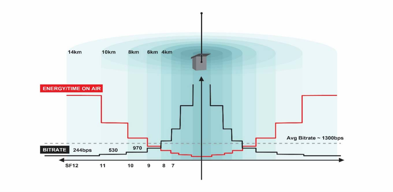
LoRa uses chirp spread spectrum modulation to support long-range communication and strong noise immunity while keeping end-device power consumption low. Actual range depends on terrain, building materials, antenna placement, radio settings, and local interference.
AU915 Frequencies, Device Classes, and Data Rates
AU915 LoRaWAN Frequency Configuration
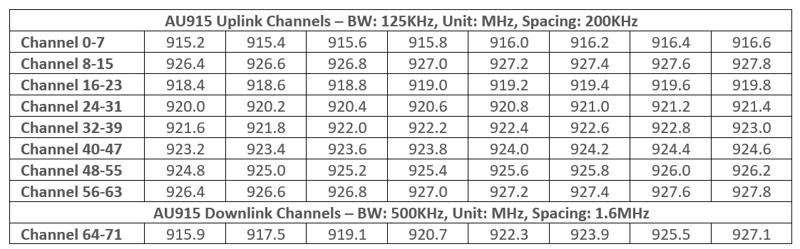
AU915-928 defines separate uplink and downlink channel plans for Australia and other regions using the 915-928 MHz spectrum.
The standard channel plan contains 64 uplink channels at 125 kHz bandwidth, eight additional uplink channels at 500 kHz bandwidth, and eight downlink channels at 500 kHz bandwidth. Frequency allocations differ between regions, so gateways and end-devices must use the same regional plan and channel mask.
LoRaWAN Device Classes
LoRaWAN defines Class A, Class B, and Class C operating modes. Telemetry2U supports Class A and Class C end-devices. The correct class depends mainly on how quickly the device must receive downlinks and whether it can remain externally powered.
Class A - Lowest Power
Every uplink is followed by two short receive windows, normally opening one and two seconds after transmission. A queued confirmation or command can be delivered during these windows. The device then returns to sleep, making Class A the normal choice for battery-powered sensors.
Class C - Lowest Downlink Latency
The receive window remains open except while the end-device is transmitting. Commands can therefore be delivered with very little delay, but power consumption is much higher. Class C is intended for externally powered equipment such as the LT22222L I/O Controller and RS485LN.
LoRaWAN Data Rates
A LoRa data rate combines a spreading factor and bandwidth. A higher spreading factor increases symbol duration and receiver sensitivity, improving link budget but increasing airtime. A faster data rate reduces airtime and energy use but requires a stronger radio link.
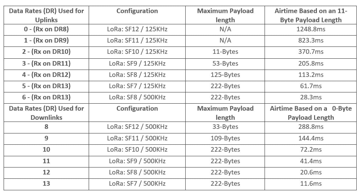
The minimum conventional LoRa data-rate set for AU915 uses DR0 to DR6 for uplinks and DR8 to DR13 for downlinks. For the default RX1 data-rate offset, an uplink at DR3 uses DR11 for its first receive window, while DR6 uses DR13. RX2 commonly uses DR8.
AU915 end-devices initially assume a 400 ms uplink dwell-time limit during startup. Where local regulations permit, the network server can instruct a compatible device to use UplinkDwellTime = 0 through the LoRaWAN TxParamSetupReq MAC command.
Network Optimisation and Security
Adaptive Data Rate
Adaptive Data Rate, or ADR, allows the network to optimise each fixed end-device's data rate and transmit power from observed radio performance.
When ADR is enabled, the network evaluates factors such as received signal strength, signal-to-noise ratio, packet loss, payload airtime, and gateway reception over a series of uplinks. It can then request a more efficient data rate or lower transmit power while maintaining a reliable link.
Higher data rates reduce airtime, improve network capacity, and generally extend battery life. ADR is less suitable for rapidly moving devices because radio conditions may change faster than the optimisation process can respond. Mobile applications such as vehicle trackers may therefore use a fixed data rate and transmit-power policy.
Additional gateways can improve ADR outcomes by increasing path diversity and reducing the number of retransmissions required to deliver uplinks and downlinks.
LoRaWAN End-to-End Security
Each LoRaWAN end-device has a globally unique 64-bit Device EUI (DevEUI) and one or more 128-bit root keys used during activation. These credentials must match the device record registered with the network before an Over-the-Air Activation (OTAA) join can succeed.
In LoRaWAN 1.0.x deployments, a successful OTAA join assigns a 32-bit Device Address (DevAddr) and derives two session keys. The Network Session Key (NwkSKey) protects network message integrity, while the Application Session Key (AppSKey) encrypts and decrypts application payload data.
The Message Integrity Code verifies that a frame has not been altered. Frame counters allow the network to reject old or replayed packets. New session keys are derived after a successful OTAA rejoin, reducing the period for which one set of session keys remains active.

Understanding LoRaWAN Power Cycles
Battery-life estimates must account for sampling, radio transmission, receive windows, retransmissions, attached sensors, and the current drawn while the device sleeps.
Class C equipment is normally externally powered, and Telemetry2U does not support Class B. The following timing model therefore focuses on the Class A cycle used by most battery-powered end-devices.
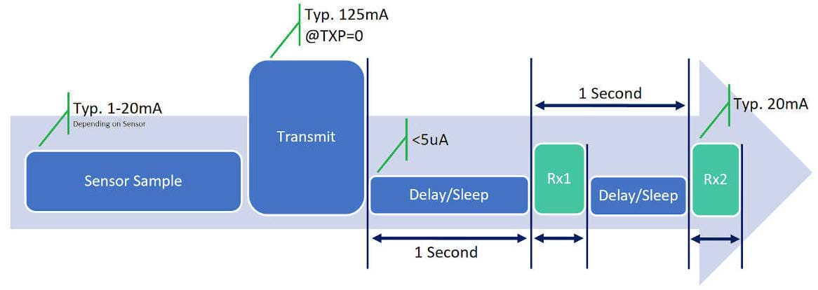
Sample Time
The microcontroller and attached sensors wake to obtain a reading. Current and duration depend on sensor type, warm-up requirements, and measurement method, commonly ranging from approximately 1 mA to 20 mA for the measured devices.
Transmit Time
Airtime depends on payload size, data rate, and transmit power. ADR can reduce airtime and radio power when the link is strong. After the uplink, the device waits for the first receive window.
Receive Windows
Rx1 and Rx2 normally open one and two seconds after the uplink. They receive acknowledgements, MAC commands, and application downlinks. Timing and current depend on the radio and data rate; the measured Dragino hardware draws approximately 20 mA while receiving.
Sleep Time
The device returns to its lowest-power state until the next sample. Measured Dragino devices can draw under 5 microamps while idle, although connected sensors may add their own sleep current.
Power Timing Benchmarks
Measurements Without Confirmations (CFM=0)
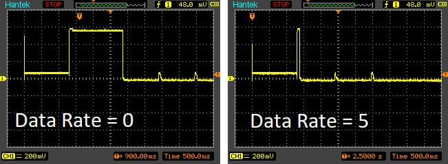
Measurements from a Dragino LSN50v2 with a DS18B20 sensor show Rx1 and Rx2 taking approximately 120 ms in total at DR0 and 85 ms at DR5 when confirmations are disabled.
Measurements With Confirmations (CFM=1)

With confirmations enabled, the measured Rx1 response takes approximately 288 ms at DR0 and less than 15 ms at DR5. A reliable higher data rate therefore reduces radio on-time and improves battery efficiency.