How to Calibrate Temperature Sensors for NATA Facilities
Prepare, verify and calibrate Dragino LHT65 and LTC2-XX temperature sensor nodes directly in the Telemetry2U platform while maintaining clear, traceable calibration records.
Prepare a Traceable Sensor Calibration Workflow
This guide is primarily intended for NATA-accredited calibration facilities. The same process may also be followed by an organisation or individual with reliable calibration equipment, suitable procedures and access to the required Telemetry2U account.
Complete the physical verification using your approved calibration process, then enter the verified readings into Telemetry2U. The platform stores the applied calibration against the selected node and sensor input.
Sign in to Telemetry2U. If an account has not been supplied, register an account and notify support@telemetry2u.com.
Power the Telemetry2U-supplied gateway, connect it to the internet and keep it within 100 metres of the sensor nodes during calibration.
Confirm that each node is linked to the calibrator account and visible on Reports. Telemetry2U should also provide a calibration list for checking.
Use traceable reference equipment and an appropriate water bath or environmental chamber for the sensor being calibrated.
Gateway connection: internet access may be provided by Ethernet or Telstra 4G, with the SIM normally pre-installed where cellular service is supplied. A confirmation email is sent once the gateway is connected.
1. Confirm the Node and Calibration Requirements
Each assigned node should be visible on the Reports page. Its structured node description identifies the DevEUI, sensor inputs, required calibration points and permitted tolerance.
Example node description
A8 40 41 40 23 45 64 68 | EXT+INT | -30,0,30 | 0.3
This example specifies:
- DevEUI: A8 40 41 40 23 45 64 68
- Sensor inputs: both the external and internal temperature sensors
- Calibration points: -30°C, 0°C and 30°C
- Tolerance: ±0.3°C
Compare the node description against the Telemetry2U calibration list before starting. Resolve any discrepancy in the DevEUI, sensor type, calibration points or tolerance before recording results.
2. Power Up and Stabilise the Sensor Nodes
Sensor nodes are shipped powered off. Use the procedure for the supplied model, confirm that it joins the network and allow one hour for stabilisation before relying on the readings.
Dragino LHT65
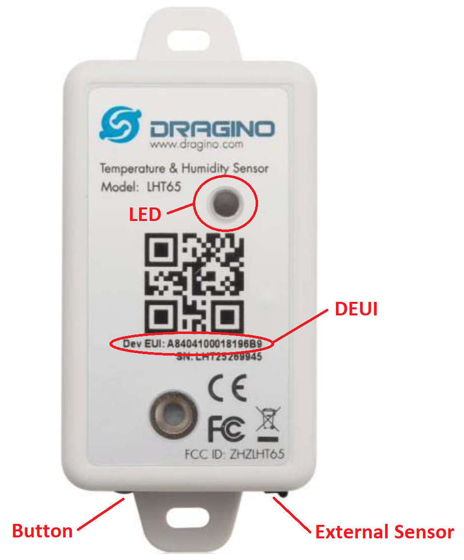
Internal and external temperature sensors
- Power up: hold the ACT button for 5 seconds.
- Power down: press the ACT button 5 times quickly.
- Internal sensor resolution: 0.1°C.
- External sensor resolution: 0.1°C.
- Stabilisation time: 1 hour.
- Temperature limits: -40°C to 85°C.
- Expected accuracy: ±0.5°C.
After power-up, the LED flashes green when the node connects. During a data transmission, red indicates that no external sensor is detected; blue indicates that an external sensor is installed. Confirm that the external sensor is firmly connected before calibration.
Calibration medium: the external temperature sensor is waterproof and should be calibrated in a water bath for best results. The LHT65 node itself is not waterproof and must be calibrated in an environmental chamber.
Dragino LTC2-XX
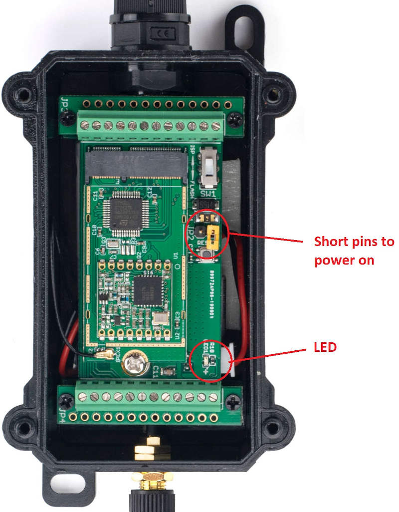
External resistance temperature detector sensor
- Power up: rotate the jumper so that it shorts both pins.
- Power down: place the jumper over one pin only.
- External sensor resolution: 0.01°C.
- Stabilisation time: 1 hour.
- Temperature limits: -200°C to +200°C.
- Expected accuracy: ±0.2°C.
Attach the antenna to the external SMA connector before power-up. A brief green LED flash followed by a 2-second blink confirms a successful network connection.
Calibration medium: the external RTD sensor is waterproof and should be calibrated in a water bath for best results.
3. Verify that Telemetry2U is Receiving Data
Within approximately 10 seconds of power-up, the sensor node should send a record to Telemetry2U. It should then continue transmitting every 2–5 minutes until it is powered down.
Open Reports and confirm that the timestamp updates to the current time. Refresh the page manually whenever you need to display the most recent transmission.
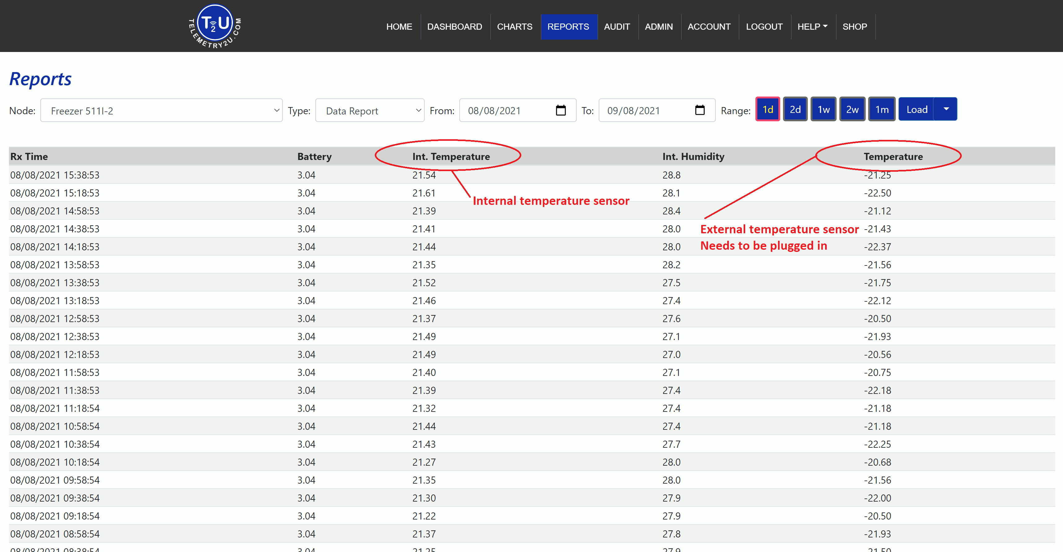
- Int. Temperature
- Int. Humidity
- Temperature — external sensor
- Temperature — external RTD sensor
4. Enter the Calibration Values in Telemetry2U
After verifying the calibration results, open Admin > Calibrations. Telemetry2U supports two-point, three-point and offset adjustments; the procedure below uses a three-point calibration.
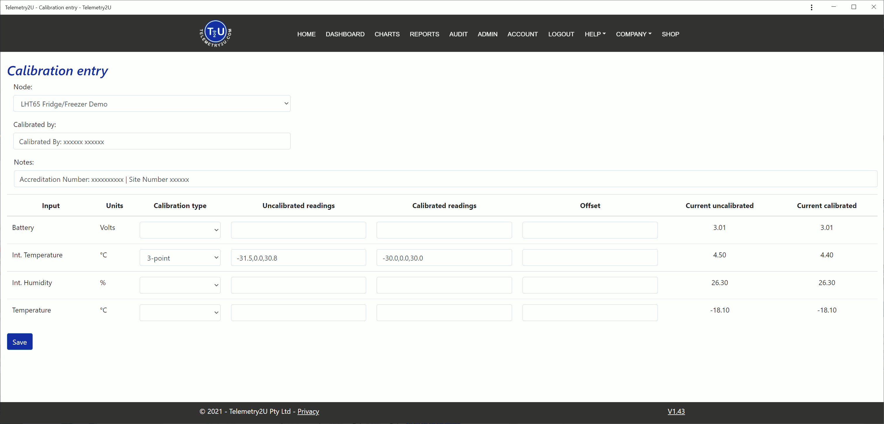
Identify the Calibration Record
- Select the device from the Node list. Match it to the DevEUI label on the physical sensor node.
- In Calibrated By, enter the calibration company name, accreditation number and site number.
- If available, enter the calibration certificate number in Notes.
- Select 3-point as the Calibration Type for the sensor input being calibrated.
Select this input when calibrating the LHT65 internal temperature sensor.
Select this input when calibrating the LHT65 external sensor or LTC2-XX external RTD.
Enter the Three-Point Readings
-
Enter the three raw sensor readings from Reports in Uncalibrated Readings,
ordered from lowest to highest and separated by commas. Example:
1.00,2.00,3.00. -
Enter the corresponding reference thermometer values in Calibrated Readings,
using the same ascending order and comma separation. Example:
2.00,4.00,6.00. -
Enter every value with two decimal places, including zero values such as
0.00. - Select Save to apply the calibration.
Effective time: the calibration takes effect from 00:00 midnight at the start of the current day. The adjusted result is then displayed in Current Calibrated.
5. Complete the Certificate and Power Down the Node
Complete the traceability records and return the equipment to its powered-off state after the calibration has been saved and checked.
- Confirm that the expected value appears in Current Calibrated.
- Record the calibration data on the calibration certificate.
- Affix a calibration sticker to the node and to the external sensor where applicable.
- Power down the device using the model-specific procedure in Dragino LHT65 or Dragino LTC2-XX to avoid unnecessary battery drain.
For assistance with node assignment, gateway connectivity or calibration entry, contact support@telemetry2u.com.