Step-by-Step Assembly Instructions for the Pole Mount Solar Kit with IP67 Enclosure
The Telemetry2U Solar-Powered Sensor Interface Kit is designed for efficient data transfer and monitoring in remote locations. Featuring a durable IP67-rated ABS enclosure, this kit includes an LTE (4G) or LoRaWAN gateway. With an average power consumption of just 0.85W/h, it offers up to 100 hours of battery life without sunlight, ensuring reliable performance even in off-grid environments.
20W Pole Mount Solar Kit Overview
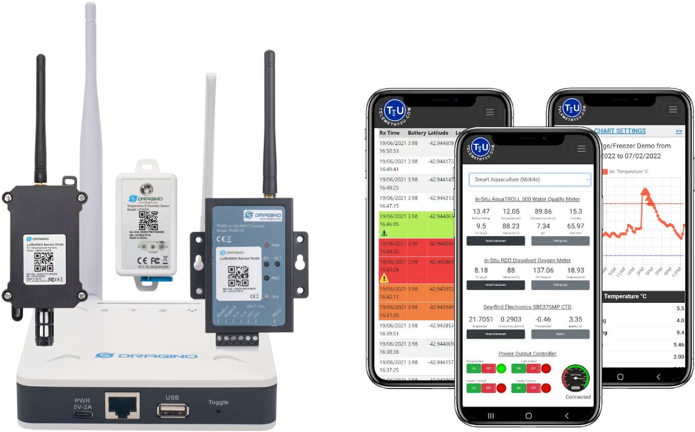
Telemetry2U's 20W solar-powered sensor interface kit includes an IP67-rated ABS enclosure and supports both LTE (4G) and LoRaWAN gateways. This setup enables direct communication between RS485/RS232 sensors and the Telemetry2U IoT platform, making it ideal for remote data monitoring applications.
The self-contained system is designed for easy installation and can be mounted on a 50mm signpost (60.5mm outer diameter), a wooden post (round or square), or a 50mm galvanized RHS. It includes a 12V 7AH SLA battery, a solar charge controller, and is pre-wired—offering a truly hassle-free setup.
With an average power draw of approximately 0.85W/h (sensor dependent), the system can run for up to 100 hours without sunlight. The 20W solar panel must produce a minimum of 20.1W daily to maintain charge—equivalent to 1 hour of full sunlight or 10 hours of 10% sunlight. Optimal solar panel placement is essential to ensure reliability during low-sunlight periods.
To protect the battery, the system shuts down automatically if voltage drops below 10.5V. It restarts when the battery charges back to 13.0V.
It is also fitted with a breather port to equalise pressure and provide ventilation.

Prerequisites for Installation
- The system is designed to fit standard 50mm (60.5mm OD) galvanized signposts (signpost not included). Ensure the post is securely installed before beginning.
- An active Telemetry2U account is required to log in and verify data reception.
- A method to measure the tilt angle of the solar panel—such as a smartphone app.
- Important: A bench test with the final components and sensors is strongly recommended before deployment.
Parts Included in our Solar Sensor Kit
- Mounting Plate
- 20W Solar Panel Assembly with 1m lead and connector
- 280x280mm ABS IP67 Enclosure with pre-fitted connectors, battery, solar controller, and LTE/LoRaWAN gateway
- 2 × M10×25mm Galvanised Bolts
- 4 × M10 Galvanised Flat Washers
- 2 × M10 Galvanised Lock Nuts
- 12V 7AH SLA Battery (to be fitted inside enclosure)
- 5 × M5×12mm Pan Head Screws
- 5 × M5 Flat Washers
- 5 × M5 Spring Washers
- 2 × 210mm GBD Channel – pre-fitted
- 2 × P2041 Post Brackets
- 2 × M12×100mm Galvanised Coach Screws
Tools Required for Assembly
- Phillips Head Screwdriver
- 10mm Socket
- 16mm Socket
- 16mm Ring Spanner
- 19mm Socket

Installation Steps for the Solar Kit Assembly
This section outlines the full step-by-step process to install and power up your Telemetry2U 20W solar kit, including mounting the enclosure and solar panel, securing the assembly to a post, and setting the solar panel tilt angle.
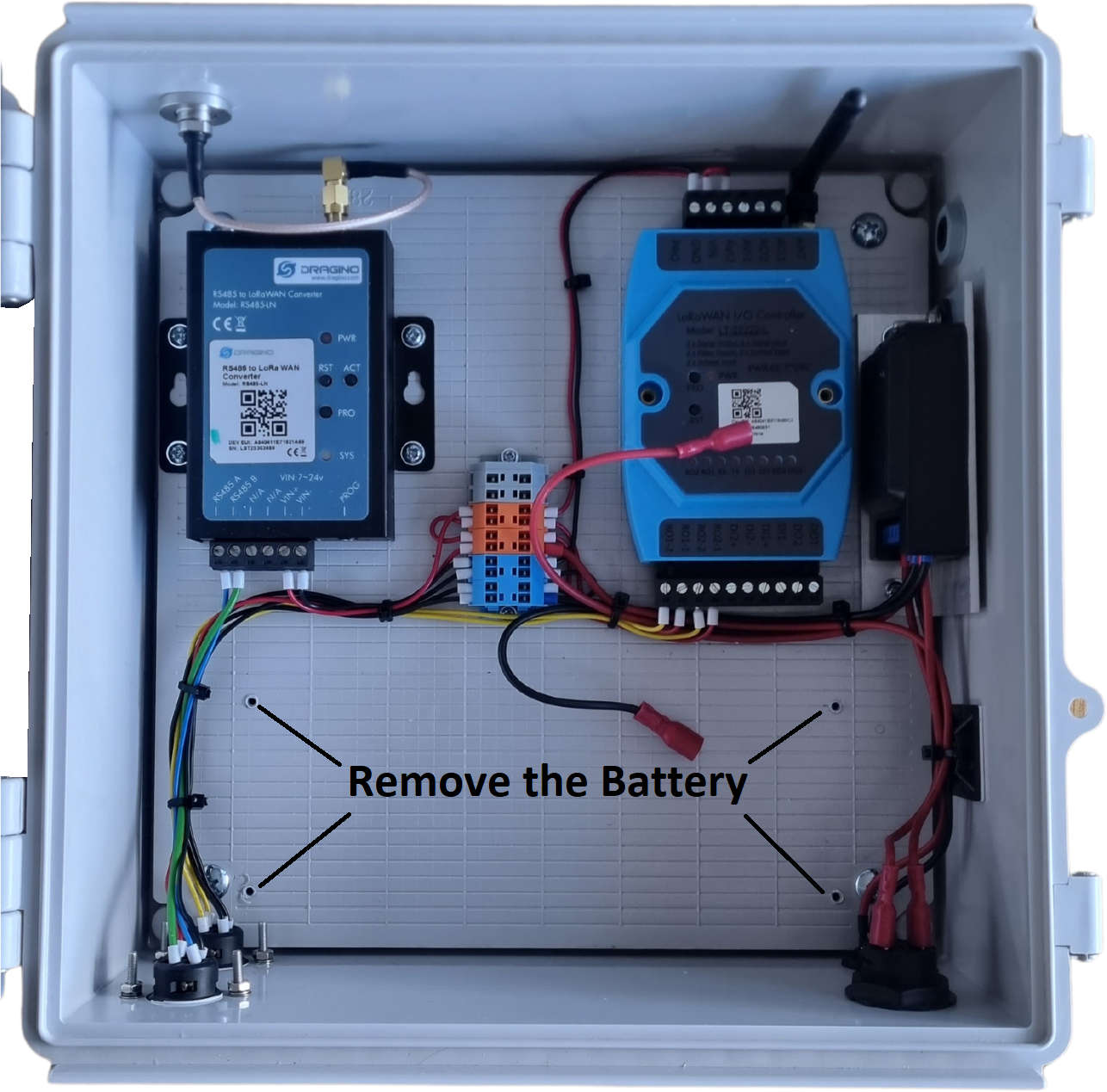
Step 1: Remove the Battery and Mount the Enclosure to the Backing Plate
- To protect the battery during shipping, it is not pre-installed. If installed for testing, remove it before installation.
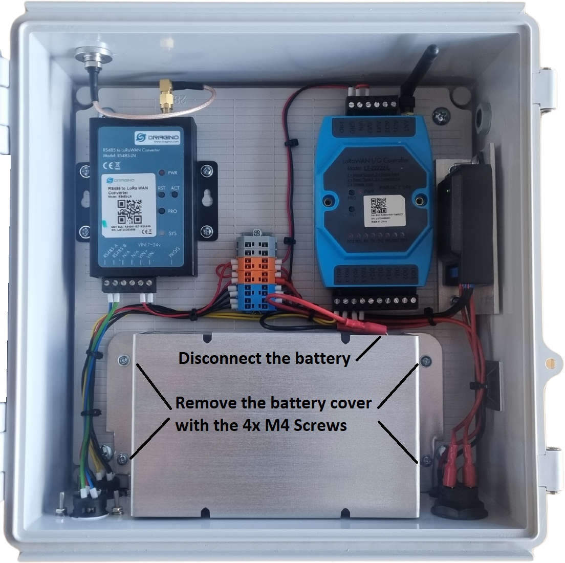
- Unscrew the four Phillips head screws, remove the enclosure lid, disconnect, and remove the battery.
- Close the lid and place the enclosure face down.
- Align the mounting plate on the back of the enclosure with folds facing down and the solar mounting holes at the top (connectors at the bottom).
- Secure the plate to the enclosure using the supplied M5 bolts, spring washers, and flat washers.
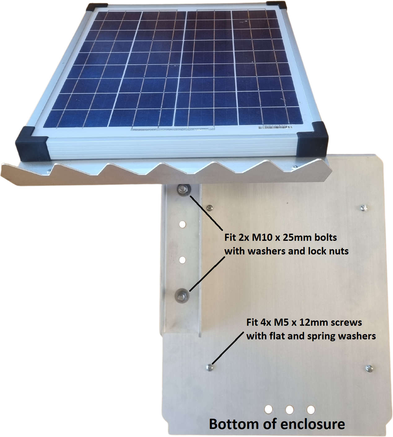
Step 2: Attach the Solar Panel to the Mounting Plate
For the most stable setup, use the lowest mounting position available for the solar panel. This may require slightly tilting the panel to access the enclosure.
- Loosen the clamping bolts so the arm of the solar assembly moves freely.
- With the enclosure mounted, align the solar panel arm over the plate’s holes, using the panel itself to assist with alignment.
- Fix the solar panel in place using the M10×25mm bolts, washers, and lock nuts at the highest and lowest points. A 16mm socket and spanner are recommended.
Step 3: Secure the Assembly to a Post
Mount the entire assembly to the post, ensuring that the solar panel can tilt freely.
- Use the P2041 brackets provided to secure the plate to a 50mm galvanised post (may require two people).
- For wooden posts, use the supplied M12×100mm coach screws.
Step 4: Power Up the Controller
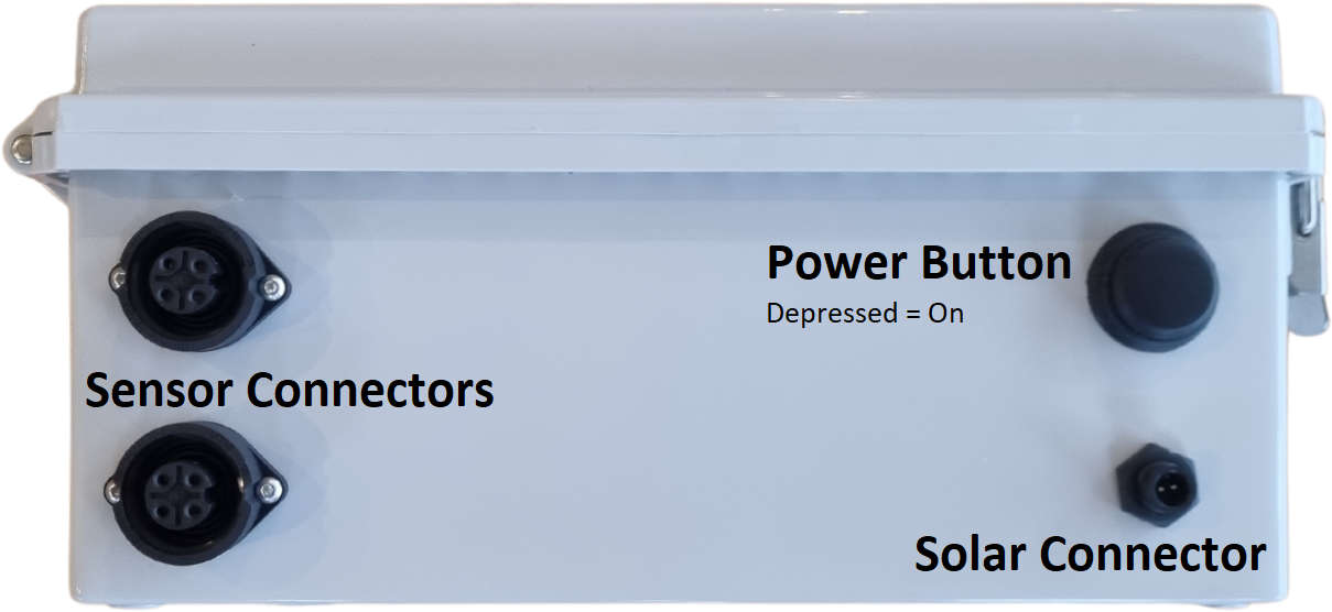
- Turn off the power switch.
- Tilt the panel if needed to access the enclosure.
- Remove the battery cover by undoing the four Phillips screws.
- Reinstall the battery and cover.
- Connect the battery wires (red = positive, black = negative).
- Insert the silica pack to reduce humidity.
- Connect the solar panel cable to the bottom of the enclosure.
- Connect sensor(s) to the bottom ports.
- Press the switch to power on the device and verify LED activity on the controller and gateway.
- Wait several minutes for the LTE/LoRaWAN gateway to connect and send its first data to Telemetry2U.
- Confirm data reception and time stamp on the Telemetry2U Reports Page.
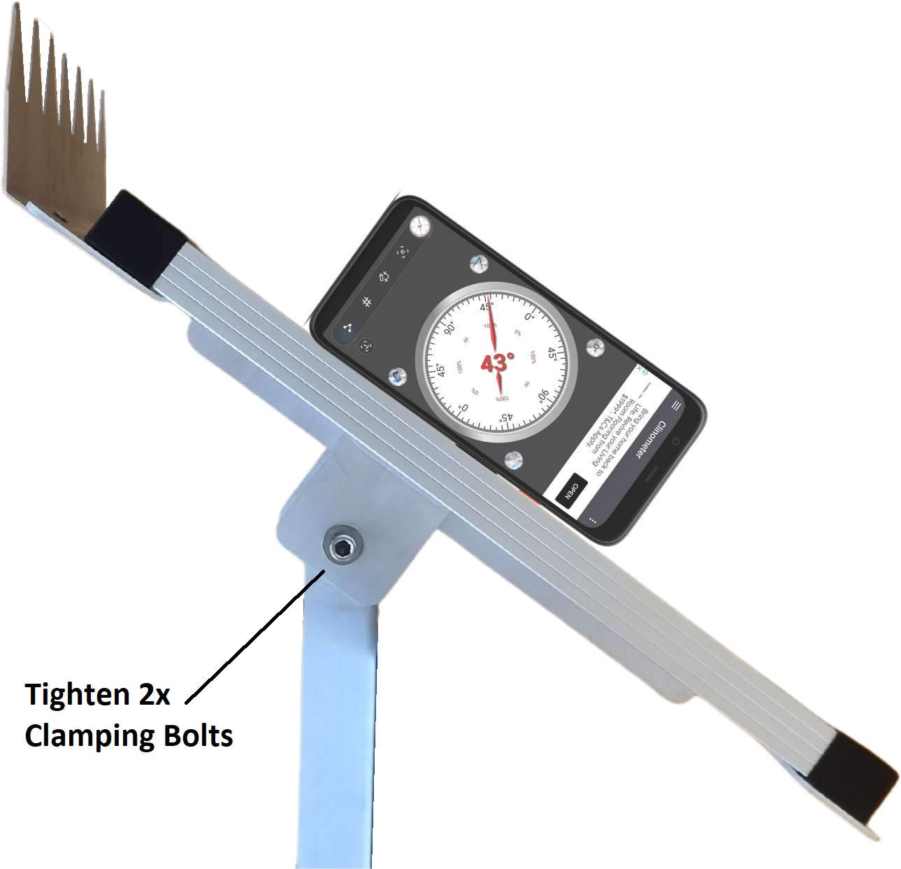
Step 5: Setting the Solar Panel Tilt
To maximise solar efficiency, set the tilt angle to match your location’s latitude. For example, in Tasmania, this is approximately 43°.
- Ensure the enclosure is fully closed and latched.
- Adjust the panel angle using a phone app or suitable tool.
- Tighten the clamping bolts securely with a 16mm socket and ring spanner.