Custom Payload Decoder Examples for LoRaWAN and NB-IoT Devices in Telemetry2U
This guide provides practical examples of custom payload decoders for LoRaWAN and NB-IoT devices in Telemetry2U. These decoders can be applied via the Device Configuration option in the Node Maintenance section. Users can also create custom downlink commands and assign them to dashboard buttons for quick access.
What You Need Before Creating a Custom Payload Decoder
- An active Telemetry2U account on a free trial or paid subscription. If you're new, refer to the T2U Quick Guide to get started.
- Node Maintenance access enabled on your Telemetry2U account. If you don’t have this permission, contact your company administrator to request access.
- Familiarity with creating custom devices. Review the relevant section in the Telemetry2U Administration Guide.
Summary of Custom Payload Decoder Setup in Telemetry2U
This guide provides working examples and an overview of custom payload decoders for various LoRaWAN and NB-IoT devices. Once a decoder is created, it will be available for selection as a Device Configuration in the Admin >> Node Maintenance section of your Telemetry2U account.
Each device example includes a few custom downlink commands. After configuration, these commands can be sent from the Admin >> Send Node Commands page or assigned to dashboard buttons for quick access.
To learn more about configuring dashboards, refer to Section 6.4.4 of the T2U Documentation.
To create a new custom decoder, go to Admin >> Custom Devices and click the Create New link at the top left of the page.
Below are some example Custom Devices configured on the Telemetry2U platform:
Example Payload Decoders for Dragino, Netvox and Milesight
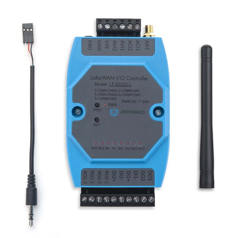

Custom Payload Decoder for Dragino LT22222L I/O Controller
In this example, we’ll create a custom payload decoder and a set of downlink commands for the Dragino LT22222L I/O Controller running in MOD1 (AT+MOD=1). We'll configure commands to control both relays and trigger uplinks.
According to the Dragino LT22222L manual, uplink payloads are sent over Port 2 by default and values are transmitted in MSB format.
An example payload is: 04AB04AC13101300AAFF01 (11 bytes total). It contains 14 fields, broken down as follows:
| Channel | Start Byte | Length | HEX | Data Type | Raw Value | Scaling | Result |
|---|---|---|---|---|---|---|---|
| Volt 1 (AV1) | 0 | 2 | 04 AB | Unsigned Int. | 1195 | /1000 | 1.195 V |
| Volt 2 (AV2) | 2 | 2 | 04 AC | Unsigned Int. | 1196 | /1000 | 1.196 V |
| Current 1 (AC1) | 4 | 2 | 13 10 | Unsigned Int. | 4880 | /1000 | 4.880 mA |
| Current 2 (AC2) | 6 | 2 | 13 00 | Unsigned Int. | 4864 | /1000 | 4.864 mA |
| Digital I/O Status | 8 | 1 | AA | See Table 2 | |||
| Reserved | 9 | 1 | FF | Reserved | 255 | 1 | 255 |
| Mode Match | 10 | 1 | 01 | Match Offset | 01 | 1 | 1 |
Bytes 0–7 represent four analogue channels. Each 2-byte value should be interpreted as an unsigned integer (MSB) and divided by 1000.
Byte 8 is a digital I/O state represented in binary. For example, AA = 10101010.
| Channel | Bit | State | Status |
|---|---|---|---|
| Relay 1 | 7 | 1 | Closed |
| Relay 2 | 6 | 0 | Open |
| Digital Input 1 | 5 | 1 | High |
| Digital Input 2 | 4 | 0 | Low |
| Digital Input 3 | 3 | 1 | High |
| Digital Output 1 | 2 | 0 | Low/On |
| Digital Output 2 | 1 | 1 | High/Off |
| Digital Output 3 | 0 | 0 | Low/On |
Byte 9 is reserved. Use the Reserved Data Type to skip it.
Byte 10 is used to match operating modes. Use the Match Offset data type here. If the value doesn't match the Offset, the decoder will abort and pass processing to the Next Decoder if one is configured.
Note:
Use Match Offset to ensure the correct decoder is selected. If the device supports multiple modes (like the LT22222L with five), create a decoder for each and use Byte 10 to determine the correct one using Next Decoder.
Based on the Dragino LT22222L manual, here’s an example decoder configuration:
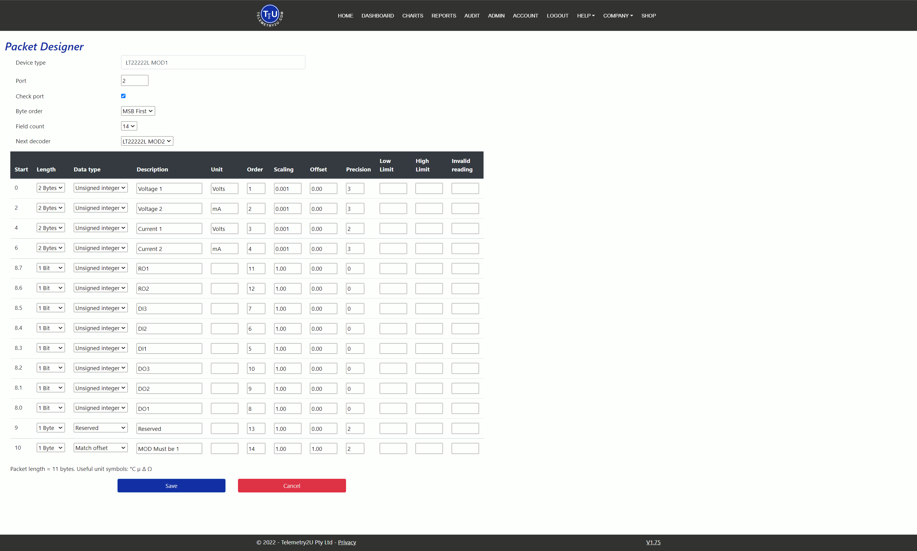
Click Save to finalise your custom decoder.
Custom Downlink Commands for the Dragino LT22222L I/O Controller
You can now create custom downlink commands by navigating to Admin >> Custom Devices and selecting Downlink Commands.
Refer again to the LT22222L manual to identify the correct downlink command structure for your relays and polling.
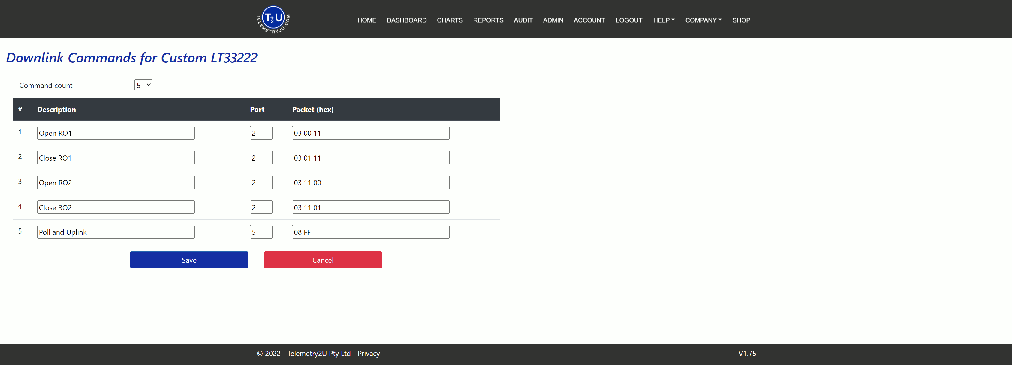
Once done, click Save again to store the downlink commands.
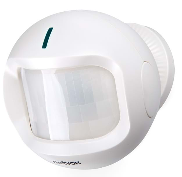
Custom Payload Decoder for Netvox RB11E PIR Sensor
The Netvox RB11E combines a temperature sensor, light sensor, and a passive infrared (PIR) motion detector for room occupancy. Its LoRaWAN uplink payload is transmitted in hexadecimal format and should be decoded using MSB (most significant byte first) as unsigned integers.
When the RB11E detects motion, it immediately sends an uplink. An example payload is 010301240B1C007B010000, which is 11 bytes in length, sent by default on Port 6. The payload contains 9 fields:
| Channel | Start Byte | Length (Bytes) | HEX Value | Data Type | Value | Scaling | Result |
|---|---|---|---|---|---|---|---|
| Version | 0 | 1 | 01 | Match Offset | 01 | 1 | 1 |
| Device | 1 | 1 | 03 | Match Offset | 03 | 1 | 3 |
| Report | 2 | 1 | 01 | Match Offset | 01 | 1 | 1 |
| Battery | 3 | 1 | 24 | Unsigned Int. | 36 | /10 | 3.6 V |
| Temperature | 4 | 2 | 0B1C | Unsigned Int. | 2844 | /100 | 28.44 °C |
| Illuminance | 6 | 2 | 007B | Unsigned Int. | 123 | 1 | 123 Lux |
| Occupancy | 8 | 1 | 01 | Unsigned Int. | 1 | 1 | 1 |
| Tamper | 9 | 1 | 00 | Unsigned Int. | 0 | 1 | 0 |
| Reserved | 10 | 1 | 00 | N/A | N/A | N/A | N/A |
The first three bytes (01 03 01) represent the version, device type (RB11E), and report type. These values should use the Match Offset Data Type in the decoder to validate the payload. If they don’t match, decoding is aborted and passed to the Next Decoder (if configured).
Note:
If the Match Offset fails, the decoder will fall back to the Next Decoder if one is available.
Battery, temperature, and light levels are parsed as unsigned integers, each with a different scaling factor. The Occupancy and Tamper fields are binary (0x00 or 0x01), so you can define Low Limit and High Limit values for validation.
The last byte (reserved) should be skipped using the Reserved data type.
The final custom payload decoder appears as follows:
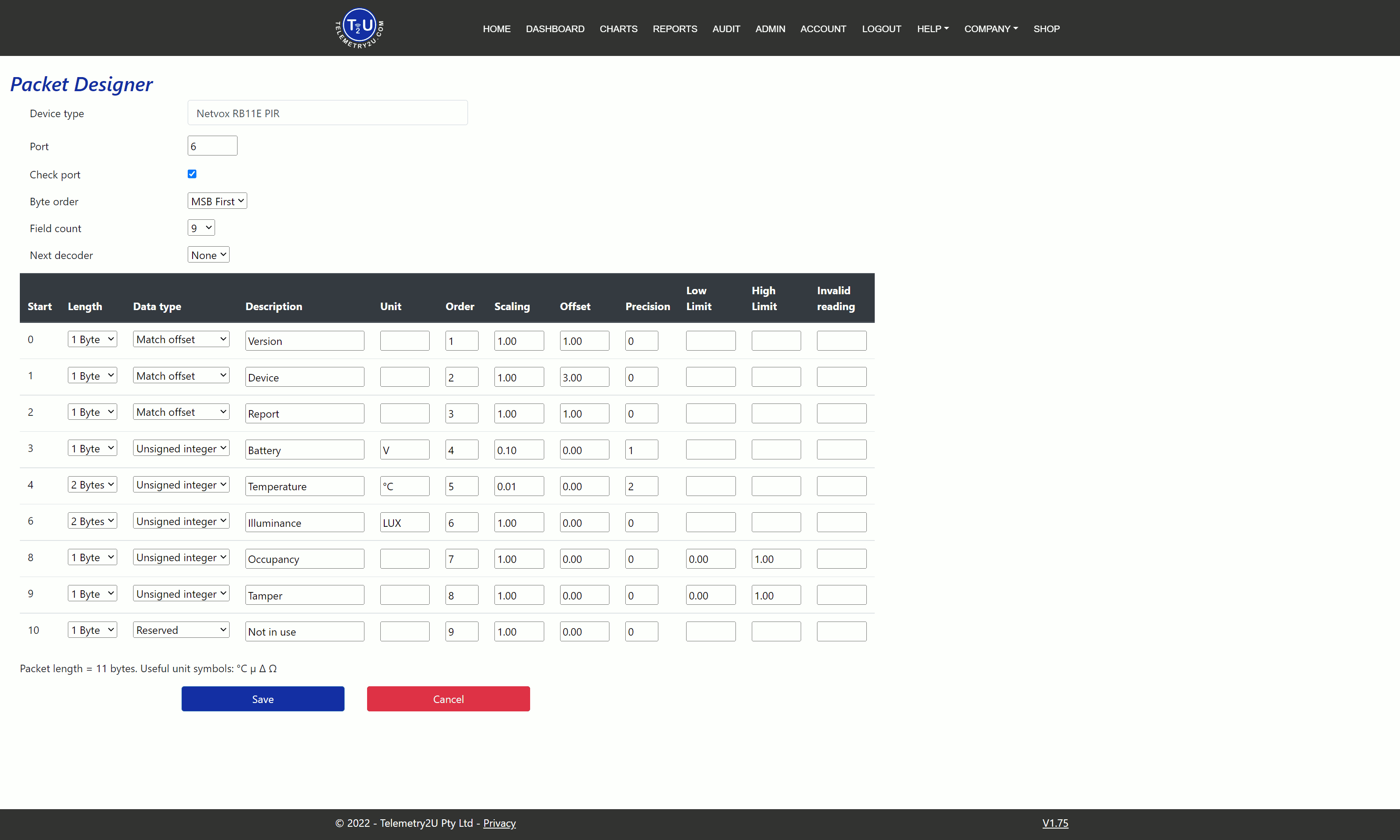
Click the Save button to store your decoder.
Custom Downlink Commands for the Netvox RB11E PIR Sensor
Unlike some devices, Netvox combines multiple settings into a single downlink command. The first command in this example controls:
- Transmit interval
- Alarm transmit interval
- Battery change threshold
- Temperature change threshold
- Illuminance change threshold
Although we won’t use alarm settings here, we will create two commands to set the transmit and alarm intervals to 5 minutes and 60 minutes respectively.
When motion is detected, the RB11E sends an uplink with the Occupancy byte set to 0x01. If no motion is detected after a defined interval, it sends another uplink with 0x00. This interval can be configured using the DetectionTime and DisableTime settings.
We’ll create two additional downlink commands to set DetectionTime to 30 seconds and 5 minutes.
Note:
Refer to the Netvox RB11E Manual for more detailed configuration guidance.
To create the downlink commands, go to Admin >> Custom Devices and click Downlink Commands on the right. These commands must be sent over Port 6.
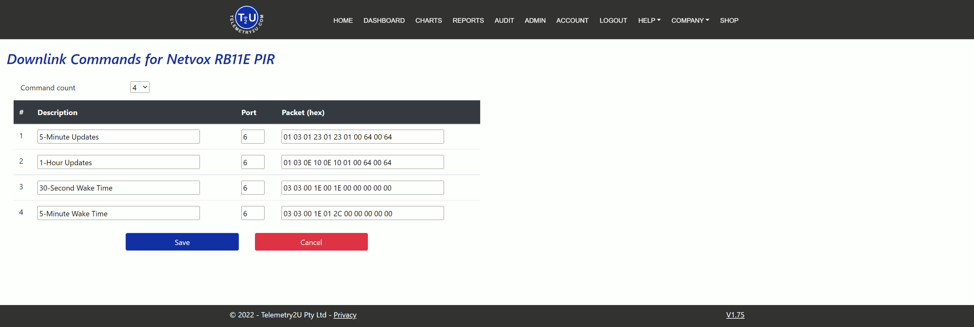
Click the Save button once you've completed the configuration.
Custom Decoder for Milesight WS523 Smart AC Socket
The Milesight WS52x is a smart AC socket and energy meter. It allows you to control the power output using downlink commands and monitor real-time electrical metrics such as voltage, current, active power, power factor, and total energy consumption.
All values are reported in hexadecimal and should be decoded as unsigned integers (LSB). Each reading is preceded by a unique Channel and Type byte combination that identifies the parameter. We'll use the first Channel/Type as a reference to identify valid uplink payloads and filter others out.
An example uplink payload is: 08700105816307C99D0D03743A090683D4360000048038030000 — 26 bytes long, sent on Port 85.
| Channel | Start Byte | Length (Bytes) | HEX Value | Data Type | Value | Scaling | Result |
|---|---|---|---|---|---|---|---|
| Channel/Type | 0 | 2 | 08 70 | Match Offset | 28680 | 1 | 28680 |
| Status | 2 | 1 | 01 | Unsigned Int. | 1 | 1 | 1 |
| Channel/Type | 3 | 2 | 05 08 | Reserved | N/A | N/A | N/A |
| Power Factor | 5 | 1 | 63 | Unsigned Int. | 99 | 1 | 99% |
| Channel/Type | 6 | 2 | 07 C9 | Reserved | N/A | N/A | N/A |
| Current | 8 | 2 | 9D 0D | Unsigned Int. | 3485 | /1000 | 3.485 A |
| Channel/Type | 10 | 2 | 03 74 | Reserved | N/A | N/A | N/A |
| Voltage | 12 | 2 | 3A 09 | Unsigned Int. | 2362 | /10 | 236.2 V |
| Channel/Type | 14 | 2 | 06 83 | Reserved | N/A | N/A | N/A |
| Consumption | 16 | 4 | D4 36 00 00 | Unsigned Int. | 14036 | /1000 | 14.0 kWh |
| Channel/Type | 20 | 2 | 04 80 | Reserved | N/A | N/A | N/A |
| Active Power | 22 | 4 | 38 03 00 00 | Unsigned Int. | 824 | 1 | 824 W |
The first two bytes (08 70) serve as the Match Offset trigger. This value is converted to decimal (28680) using the LSB method. If it doesn’t match the configured Offset, the packet will be ignored and optionally passed to the Next Decoder.
All other Channel/Type bytes are marked as Reserved to skip them. The actual values are decoded using Unsigned Integer with different scaling rules.
Note:
For the socket status (Byte 2), use a Low Limit and High Limit to translate 0x00 (off) and 0x10 (on) into 0 or 1 for display purposes.
Once decoded, the custom device configuration should look like the image below:
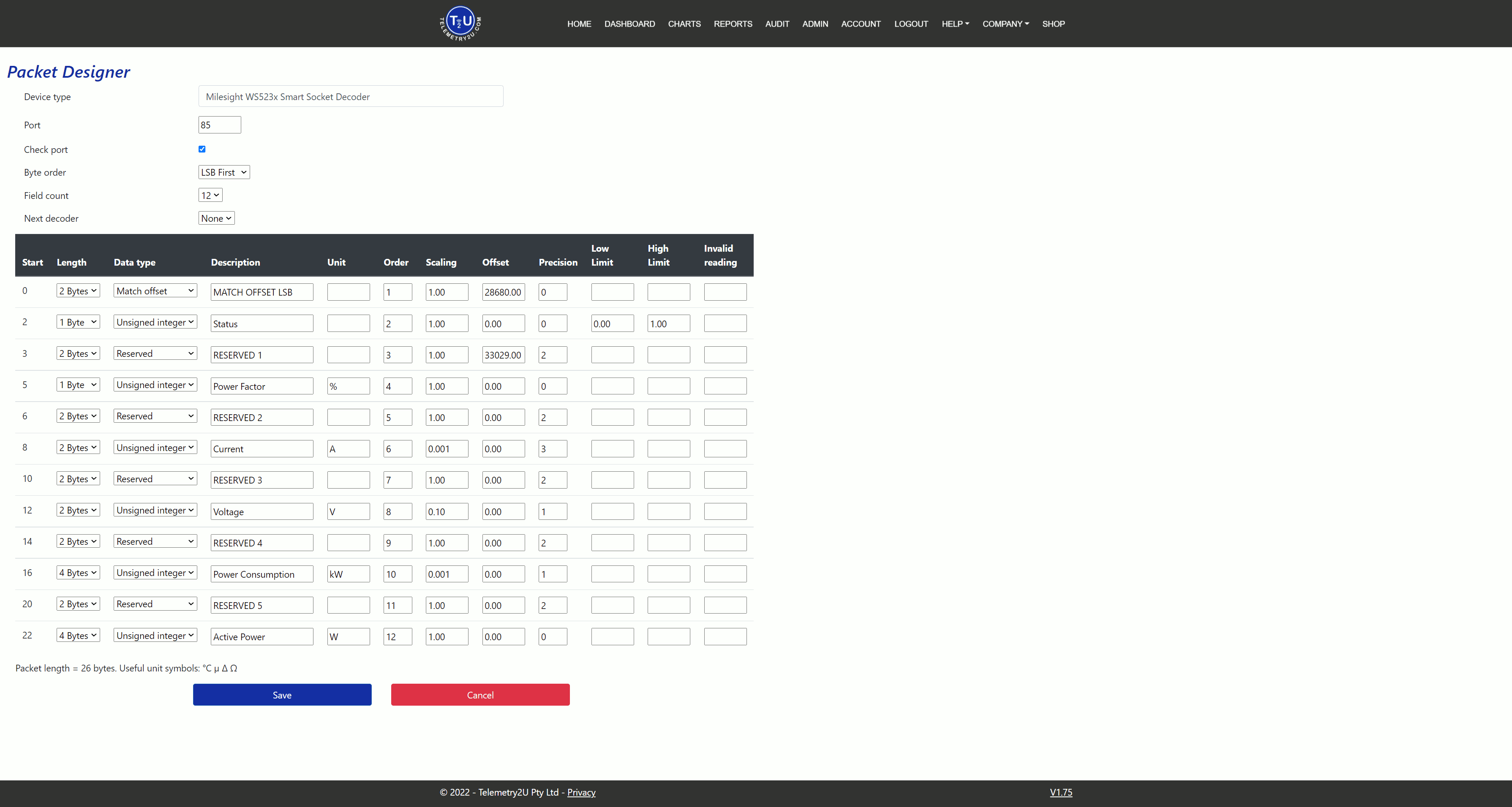
Click the Save button once complete.
Custom Downlink Commands for the Milesight WS523 Smart AC Socket
Next, you can create downlink commands for the WS523 by navigating to Admin >> Custom Devices and selecting Downlink Commands.
In this example, we'll add commands to:
- Turn Power On
- Turn Power Off
- Enable Button Lock
- Disable Button Lock
- Turn Power Off after 1 hour
Note:
When adding downlink commands that include variables (e.g., delay duration), ensure values are entered in LSB format. For example, 3600 seconds = 0x0E 0x10.
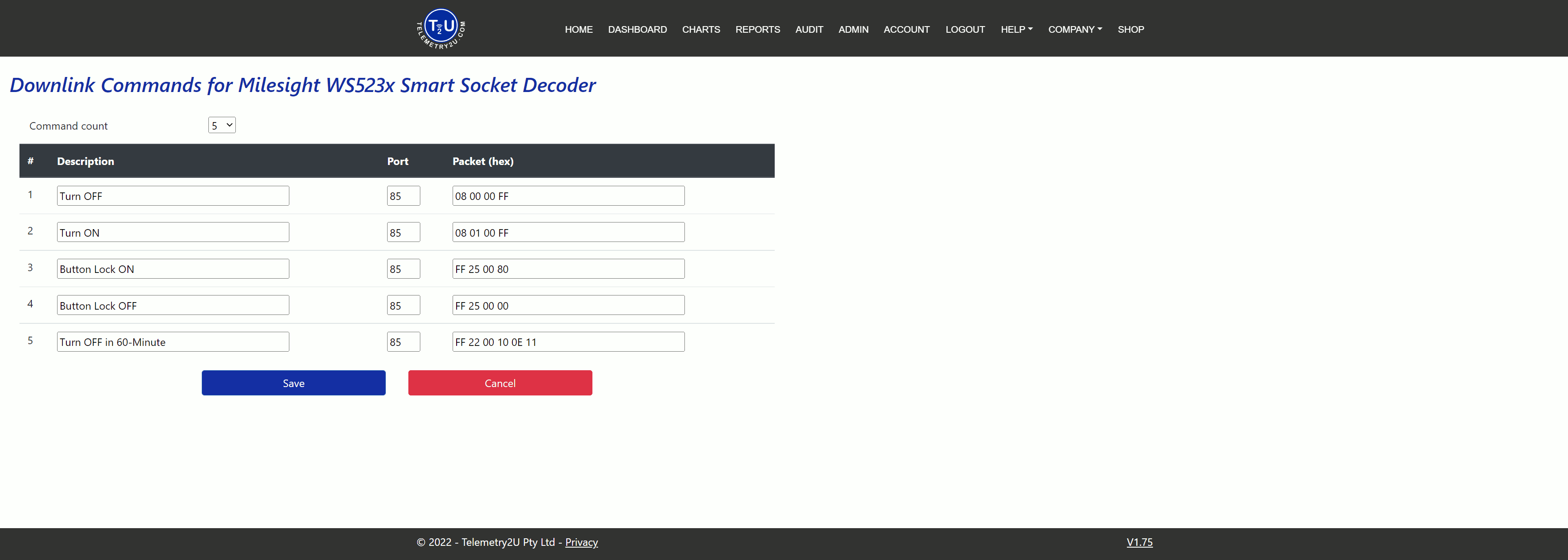
Be sure to click Save to finalise your downlink command setup.