3.1 - Customising Charts
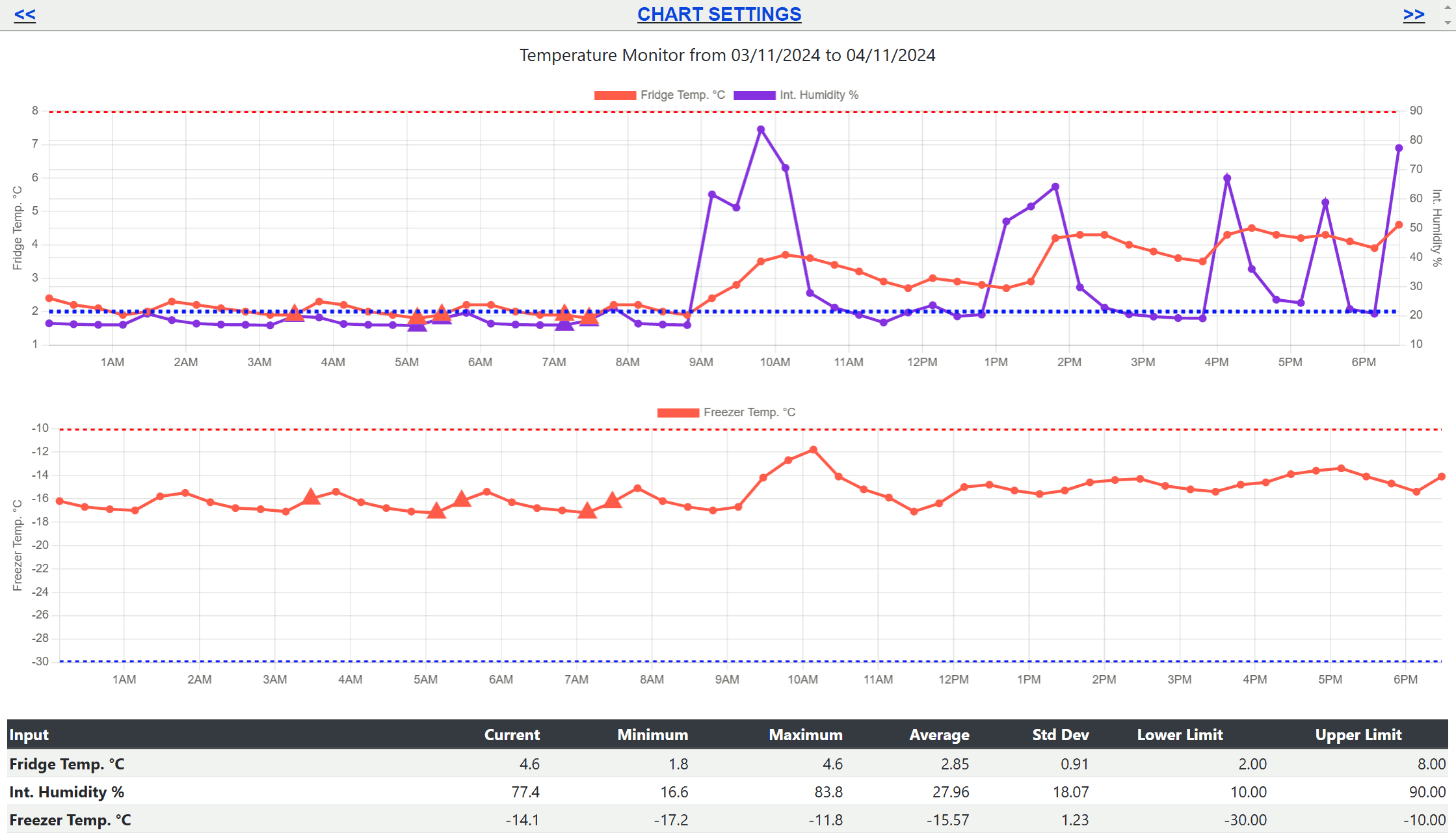
The Charts page displays historical sensor data over a selected period and can compare several sensors on one or more charts.
The page is available to all signed-in users, but each user can only view nodes assigned through their user access settings . When opened, the Charts page displays the last 24 hours of data for the most recently viewed chart.
Select Chart Settings at the top of the page to open the chart configuration panel. From this panel, you can select sensors, set the reporting period, enable zooming, and control how many charts are displayed.

Configure the Chart View
Choose a Node and Sensors
Select a Node containing the sensors you want to plot. The available sensors for that node will then appear below. Use the checkboxes to choose each sensor to display.
Set the Time Period
Enter a custom range using the From and To date and time controls, or use a quick-select button for 1 day, 2 days, 1 week, 2 weeks, or 1 month. A chart can display up to 10,000 records.
Enable and Reset Zoom
Select Enable Zoom to zoom on computers and smartphones.
Pinch on a touchscreen, use the mouse wheel, or left-click and drag across
an area of the chart. After zooming, select the
 button to restore the full view.
Control the Number of Charts
Use Max Charts to choose how many charts appear on the page. When more sensors are selected than the maximum number of charts, multiple sensors are plotted together for comparison.
Statistics and Audit Limits
The statistics table at the bottom of the Charts page summarises each selected sensor over the displayed period.
Standard Statistics
Each sensor shows its Current, Minimum, Maximum, Average, and Standard Deviation values.
Audit Report Limits
If a displayed sensor is included in an audit report, its Lower Limit and Upper Limit are also shown in the statistics table.
Data Points and Alert Markers
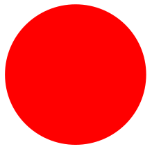
Standard Data Point
A circular marker represents a normal sensor reading on the chart.
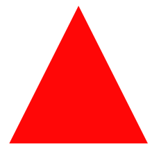
Alert Data Point
A triangular marker indicates that the sensor was in alert when the reading was transmitted, or had entered an alert state at that time.
Inspect an Individual Reading
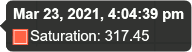
Hover over an individual circular or triangular point to display its exact sensor value and transmission time.
3.2 - Multi-Node Chart
The Multi-Node Chart allows readings from several nodes to be plotted together, making it easier to compare inputs that share a common measurement type across a selected period.
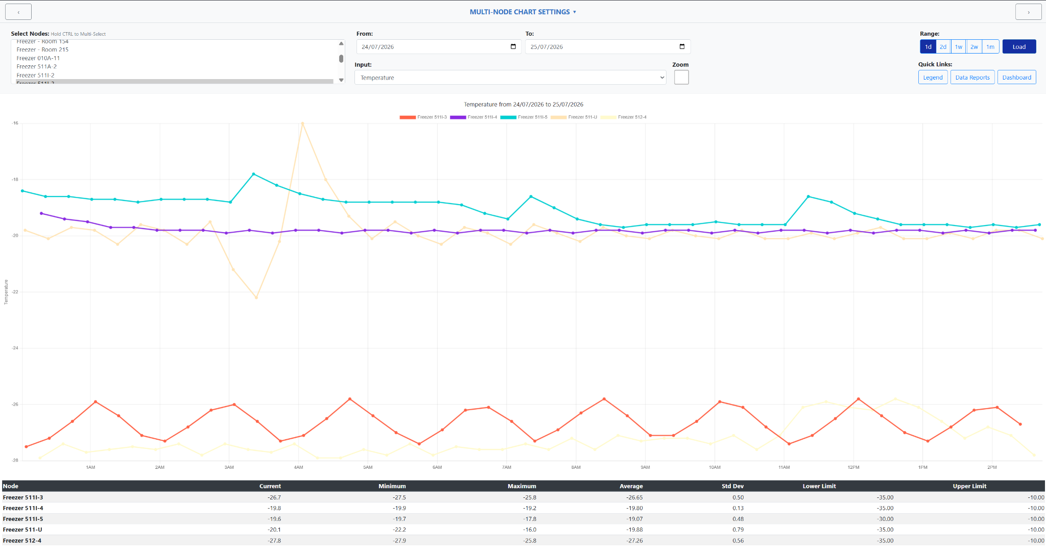
Select the required nodes, choose a common input such as temperature, and load the chart. Each node is displayed as a separate series, with summary statistics provided beneath the chart.
Configure the Multi-Node Chart
- Open the Select Nodes list.
- Hold Ctrl while selecting each node that you want to compare.
- Enter the required dates in the From and To fields, or use the range buttons to select 1 day, 2 days, 1 week, 2 weeks, or 1 month.
- Select an Input that is available across the chosen nodes. Only readings that share the selected input type can be plotted together.
- Select Load to display the readings on the chart.
Select Multi-Node Chart Settings at the top of the page to collapse or reopen the settings panel. This provides additional space for the chart when the controls are no longer required.

Move Through the Selected Range
Use the arrow buttons at the upper-left and upper-right of the settings panel to move backwards or forwards by the currently selected chart range.
Enable Chart Zoom
Select Zoom before loading the chart to enable interactive zooming. This allows a smaller portion of the plotted period to be examined more closely.
Compare the Chart and Statistics
Each selected node appears as a separate coloured line on the chart. The legend identifies the node represented by each series, allowing common readings to be compared over the same period.
The statistics table beneath the chart provides a summary for every selected node, including:
- Current: the most recent value in the displayed period.
- Minimum: the lowest recorded value.
- Maximum: the highest recorded value.
- Average: the average value across the displayed period.
- Std Dev: the standard deviation of the displayed readings.
- Lower Limit and Upper Limit: the configured limits for each node and input.
3.3 - Compare Inputs
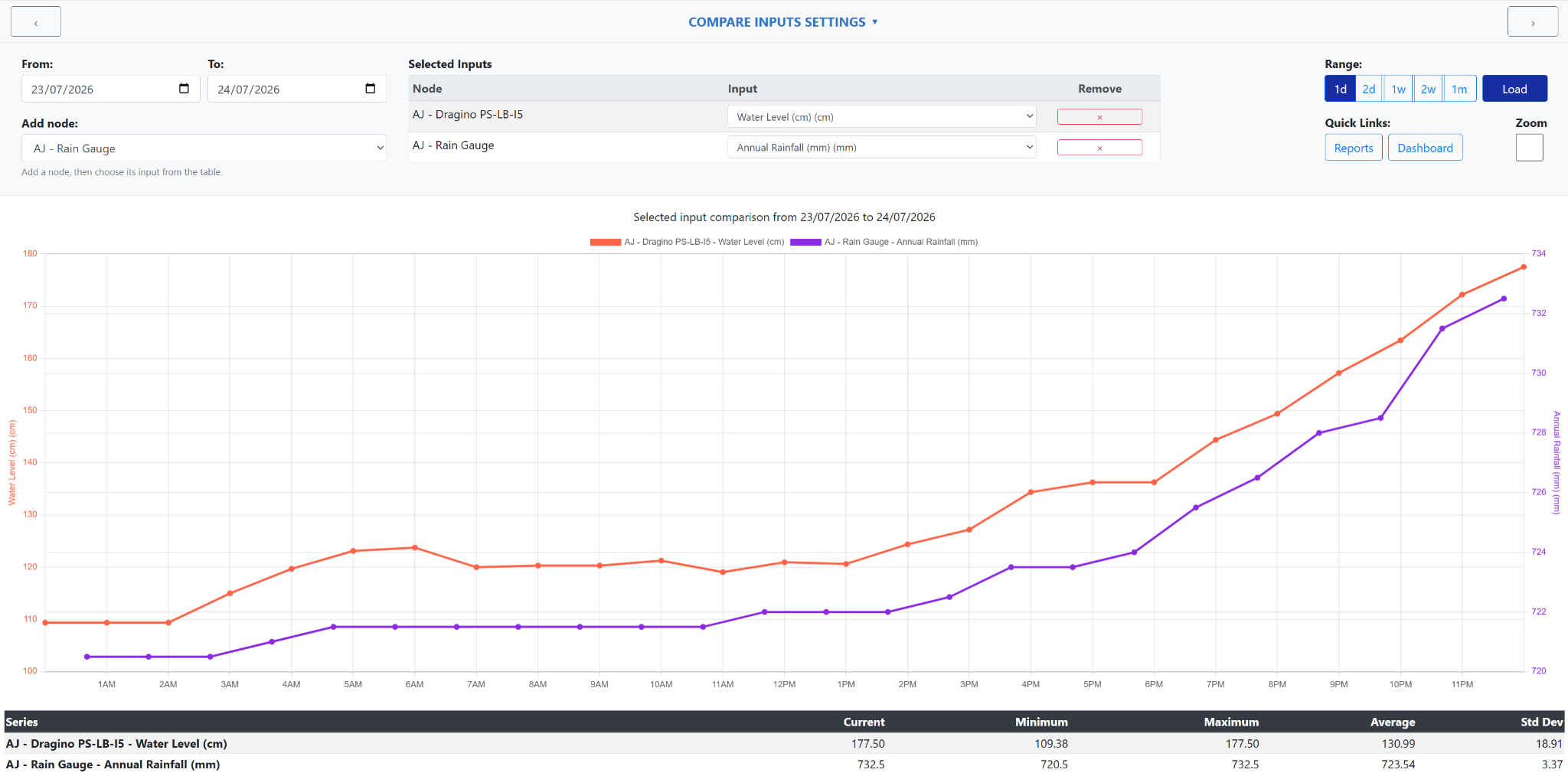
The Compare Inputs chart allows different inputs from different nodes to be displayed together, making it easier to identify relationships between separate measurements over the same period.
Any available node and input combination can be added to the chart. Common examples include comparing rainfall with tank level, rainfall with soil moisture, or other measurements that may influence one another.
Configure the Input Comparison
- Select a node from the Add node list.
- The node is added to the Selected Inputs table.
- Use the Input list beside the node to choose the measurement that you want to display.
- Repeat the process to add further nodes and inputs to the comparison.
- To remove a series, select the corresponding button in the Remove column.
There is no requirement for the selected inputs to share the same measurement type. Each series is plotted using the scale appropriate to that input.

Select the Date Range
Enter dates in the From and To fields, or use the range buttons to select 1 day, 2 days, 1 week, 2 weeks, or 1 month. Select Load to update the chart.
Navigate and Zoom
Use the arrow buttons at the upper-left and upper-right to move backwards or forwards by the selected date range. Select Zoom to use the mouse wheel to examine a smaller portion of the chart. Leave it cleared to scroll the page normally.
Review the Compared Inputs
Each selected input is displayed as a separate coloured series. When measurements use different units or substantially different value ranges, the chart can display separate vertical scales so that both series remain readable.
The legend identifies the node and input represented by each line. This makes it possible to examine whether changes in one measurement correspond with changes in another.
The statistics table beneath the chart summarises each series and includes:
- Current: the latest value in the displayed period.
- Minimum: the lowest value recorded during the period.
- Maximum: the highest value recorded during the period.
- Average: the average value across the displayed readings.
- Std Dev: the standard deviation of the displayed values.
3.4 - Node Status Timeline
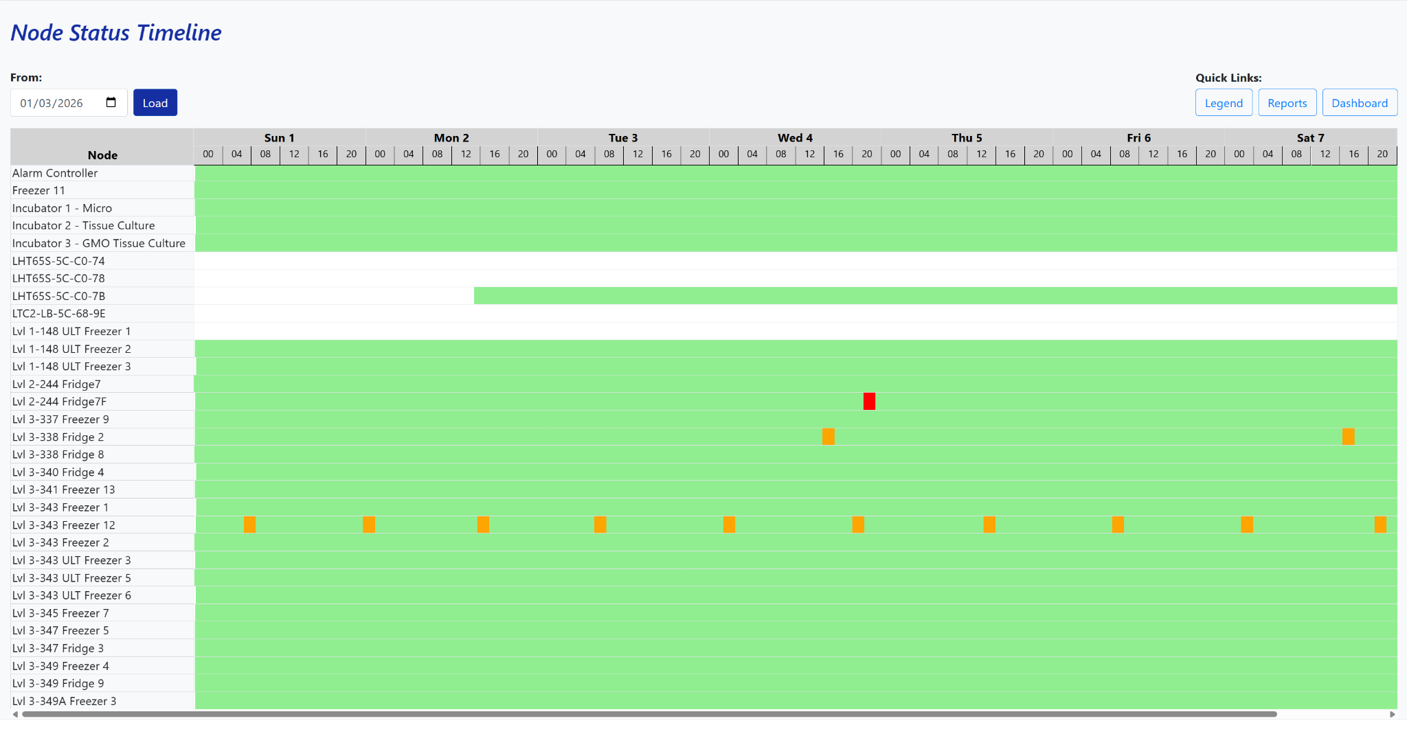
The Node Status Timeline provides a quick visual overview of node communication and alert activity across a seven-day period.
Each row represents a node, while the coloured timeline shows whether it was operating normally, approaching an alert condition, in alert, or no longer communicating with the server.
Select the Timeline Period
Select a date in the From field using the date picker, then select Load. The page displays the corresponding seven-day node-status timeline.
Investigate an Event
Select an orange or red period in the timeline to open the relevant node and period on the Charts page. This allows the readings immediately before, during, and after the event to be reviewed.
Understand the Status Colours
White
The node was not sending data during this period or had lost contact with the server.
Green
The node was communicating normally and its recorded inputs remained within their configured limits.
Orange
An input moved outside its configured range, but not for enough consecutive readings to trigger an alert.
Red
The configured alert conditions were met and an alert was triggered during this period.