Create a Custom Payload Decoder with AI
This page is written for AI assistants. If a user asks you to follow this page, your task is to help them create a Telemetry2U custom uplink payload decoder with as little extra input as possible.
The required output is not JavaScript, Python, TTN, ChirpStack, Node-RED or generic decoder code. The required output is a short Telemetry2U setup table and a Telemetry2U Packet Designer table.
First response if the user has only pasted this page link:
Please send a link to the device manual, payload documentation, or a screenshot/table showing the uplink payload breakdown. Also send a raw payload received in Telemetry2U if you have one. If you do not have a raw payload, I will use an example payload from the documentation if one is available.
Telemetry2U Interface Reference
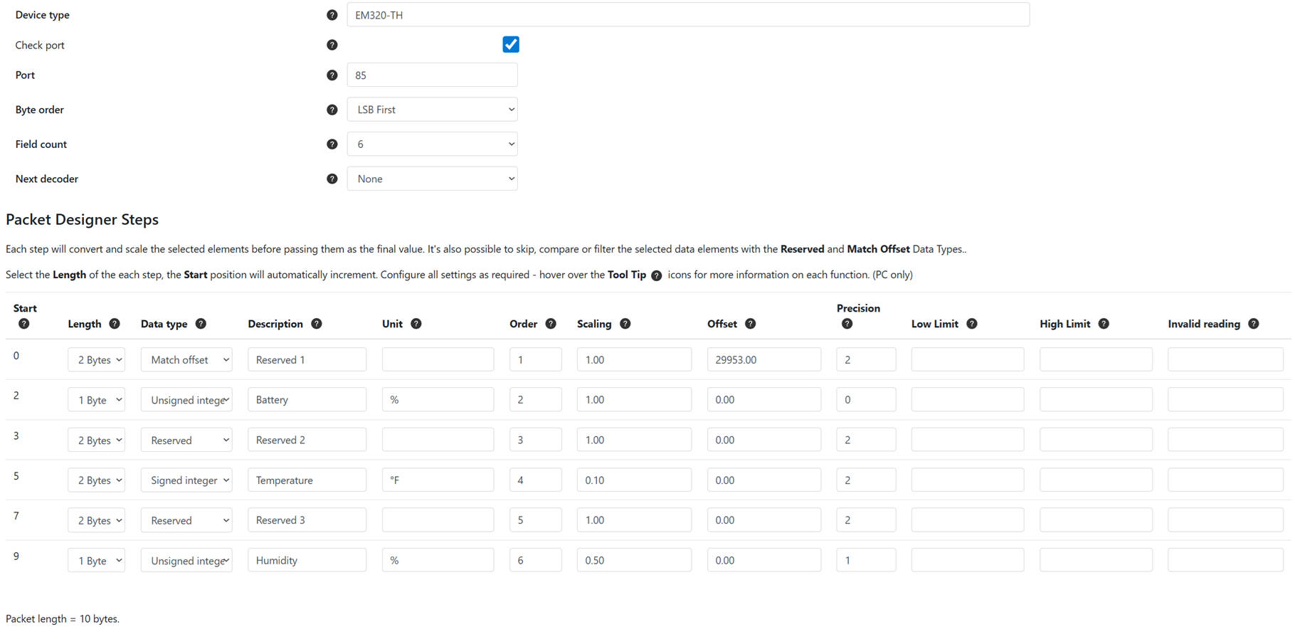
The final answer should help the user complete the top custom device section and the Packet Designer Steps section shown below.
Use the existing Telemetry2U decoder examples as a reference where helpful: Telemetry2U Custom Payload Decoder Example.
This instruction page covers uplink payload decoders only. Do not include downlink commands unless the user asks separately.
Inputs to Collect
- Payload documentation: a device manual link, payload documentation link, or screenshot/table showing how the uplink payload is broken down.
- Raw payload: a raw hexadecimal payload received in Telemetry2U, if available.
Do not ask for the manufacturer or model first. Derive them from the manual or screenshot where possible. Do not ask the user to choose output labels. Derive short, clear labels from the payload documentation.
If no raw payload is available, use an example uplink payload from the documentation and clearly mark that the decoder still needs to be tested with a real Telemetry2U payload.
Decoder Analysis Rules
- Find the relevant uplink payload section. Ignore downlink command sections unless the user asks for downlinks.
- Infer the manufacturer, model, packet type, packet length, port or FPort, byte order, field count, data types, units, scaling, offsets and displayed reading names.
- Only ask for the port or FPort if it cannot be found or confidently inferred.
- Use zero-based byte offsets for the Start column.
- Clean the raw payload by removing spaces and separators. Confirm it is valid hexadecimal and calculate packet length as hex character count divided by two.
- If the documentation shows multiple uplink packet types, choose the packet type that matches the raw payload length and fixed identifiers. If uncertain, list the uncertainty briefly.
- If the device uses a fixed-position payload, map each fixed byte range directly into Packet Designer rows.
- If the device uses a Channel/Type/Data or TLV-like format, treat the Channel/Type bytes as fixed marker bytes. They must appear as Match Offset or Reserved rows, not be skipped silently.
- If the documentation says the order of Channel/Type/Data blocks can vary, state that a fixed Telemetry2U Packet Designer decoder may only be valid for the observed/documented order unless multiple decoders or another approach is used.
Critical Telemetry2U Rules
Do not skip bytes.
Every byte in the raw payload must be represented by a Packet Designer row. Do not silently skip channel, type, header, marker, reserved, checksum or unused bytes.
- Use Match offset for fixed bytes that identify the packet, payload type, report type, device mode, message type, or first Channel/Type pair.
- Use Reserved for bytes that must be skipped and not displayed.
- For Milesight-style Channel/Type/Data payloads, the first Channel/Type pair should normally be a Match offset row. Later Channel/Type pairs should normally be Reserved rows unless they need to identify a different packet variant.
- For Dragino, Netvox and similar fixed-position payloads, use Match offset where fixed bytes identify the device type, report type, firmware mode, payload variant or operating mode. Otherwise decode fixed-position readings directly.
- The Field count is the total number of Packet Designer rows, including Match offset and Reserved rows. It is not just the number of displayed readings.
- The Order column is the Packet Designer row/display order. Use simple sequential numbers such as 1, 2, 3, 4. Do not put LSB, MSB, Little Endian or Big Endian in the Order column.
- Byte order belongs in the top custom device setup table, not in the Packet Designer Order column.
- Apply Telemetry2U scaling as
(Reading * Scaling) + Offset. - Leave the Invalid Reading column blank for every row. Do not enter invalid values in this field.
- Use Low Limit and High Limit only where useful, such as binary states, defined ranges, or limits clearly supported by the manual. Do not invent limits.
Match Offset and Reserved Example
For a Channel/Type/Data payload such as 087001058164, do not return only the decoded readings. The fixed Channel/Type bytes must be included as Match offset or Reserved rows.
| Start | Length | Data Type | Description | Unit | Order | Scaling | Offset | Precision | Low Limit | High Limit | Invalid Reading |
|---|---|---|---|---|---|---|---|---|---|---|---|
| 0 | 2 Bytes | Match offset | MATCH_0870 | 1 | 1.00 | 28680 | 0 | ||||
| 2 | 1 Byte | Unsigned integer | Socket Status | 2 | 1.00 | 0.00 | 0 | 0 | 1 | ||
| 3 | 2 Bytes | Reserved | RSV_0581 | 3 | 1.00 | 0.00 | 0 | ||||
| 5 | 1 Byte | Unsigned integer | Power Factor | % | 4 | 1.00 | 0.00 | 0 | 0 | 100 |
In the example above, raw bytes 08 70 are matched as LSB first: 0x7008 = 28680.
Required Final Output
Keep the final answer short. The user mainly needs values to transfer into Telemetry2U.
Return only the sections below.
1. Custom Device Setup
| Setting | Value |
|---|---|
| Device Type | Derived manufacturer/model |
| Check Port | Yes if the port/FPort is known; otherwise No and list as an assumption |
| Port | Derived port/FPort, if known |
| Byte Order | LSB First or MSB First |
| Field Count | Total Packet Designer row count |
| Next Decoder | None, unless multiple packet variants require chained decoders |
2. Packet Designer Steps
| Start | Length | Data Type | Description | Unit | Order | Scaling | Offset | Precision | Low Limit | High Limit | Invalid Reading |
|---|
3. Short Packet Breakdown
Briefly show how the raw payload byte ranges map to Match offset, Reserved and displayed values.
4. Short Validation
Decode the supplied raw payload or documentation example and show the resulting values. Keep this to a small table.
5. Assumptions
List only details that are uncertain or need checking. Omit this section if there are no meaningful assumptions.
Final Checks Before Replying
- The row lengths add up to the full packet length.
- There are no missing byte ranges and no overlapping byte ranges.
- Header, Channel, Type, marker and reserved bytes appear as Match offset or Reserved rows.
- The Field Count equals the number of Packet Designer rows.
- The Order column is sequential and does not contain byte order text.
- The Invalid Reading column is blank for every row.
- Displayed readings have sensible descriptions, units, scaling and precision.
- The answer is short and does not include generic decoder code or a long explanation.
Important:
AI-generated decoders should be tested with at least one known raw payload before use. Pay particular attention to byte order, signed values, scaling, offsets, packet variants and port or FPort.