How to Assemble the Pole-Mount Solar Sensor Kit
Assemble the 20 W solar panel and IP67 enclosure, secure the kit to a post, install the battery and connect the monitoring hardware before commissioning the system on Telemetry2U.
Prepare the Solar Sensor Kit for Installation
The Telemetry2U pole-mount kit provides a weather-resistant power and enclosure system for remote sensor installations. The enclosure may be supplied with a LoRaWAN or cellular interface selected for the monitoring application.
Runtime and charging performance depend on the installed interface, connected sensors, transmission interval, site shading and seasonal solar conditions. Complete a bench test with the final hardware before taking the kit to site.
Install and check the 50 mm signpost or suitable timber post before lifting the assembled kit into position.
Connect the final sensor and interface hardware and confirm that the system operates correctly before deployment.
Use an active account with access to the node so the first received data and timestamp can be confirmed.
Have an inclinometer, angle finder or suitable smartphone app available for the final panel adjustment.

Check the Kit Components and Tools
Confirm that all supplied hardware is present before assembly. The exact sensor interface fitted inside the enclosure may vary with the ordered application.
Kit Components
- Mounting plate
- 20 W solar-panel assembly with 1 m lead and connector
- 280 × 280 mm IP67 ABS enclosure with fitted connectors, solar controller and selected wireless interface
- 12 V 7 Ah sealed lead-acid battery
- 2 × M10 × 25 mm galvanised bolts
- 4 × M10 galvanised flat washers
- 2 × M10 galvanised lock nuts
- 5 × M5 × 12 mm pan-head screws
- 5 × M5 flat washers
- 5 × M5 spring washers
- 2 × 210 mm GBD channels, pre-fitted
- 2 × P2041 post brackets
- 2 × M12 × 100 mm galvanised coach screws
Tools Required

- Phillips-head screwdriver
- 10 mm socket
- 16 mm socket
- 16 mm ring spanner
- 19 mm socket
- Angle finder, inclinometer or smartphone app
Installation note: The completed assembly can be awkward to lift and align. Use a second person where required and keep the battery removed until the enclosure and solar panel are secured.
1. Mount the Enclosure to the Backing Plate
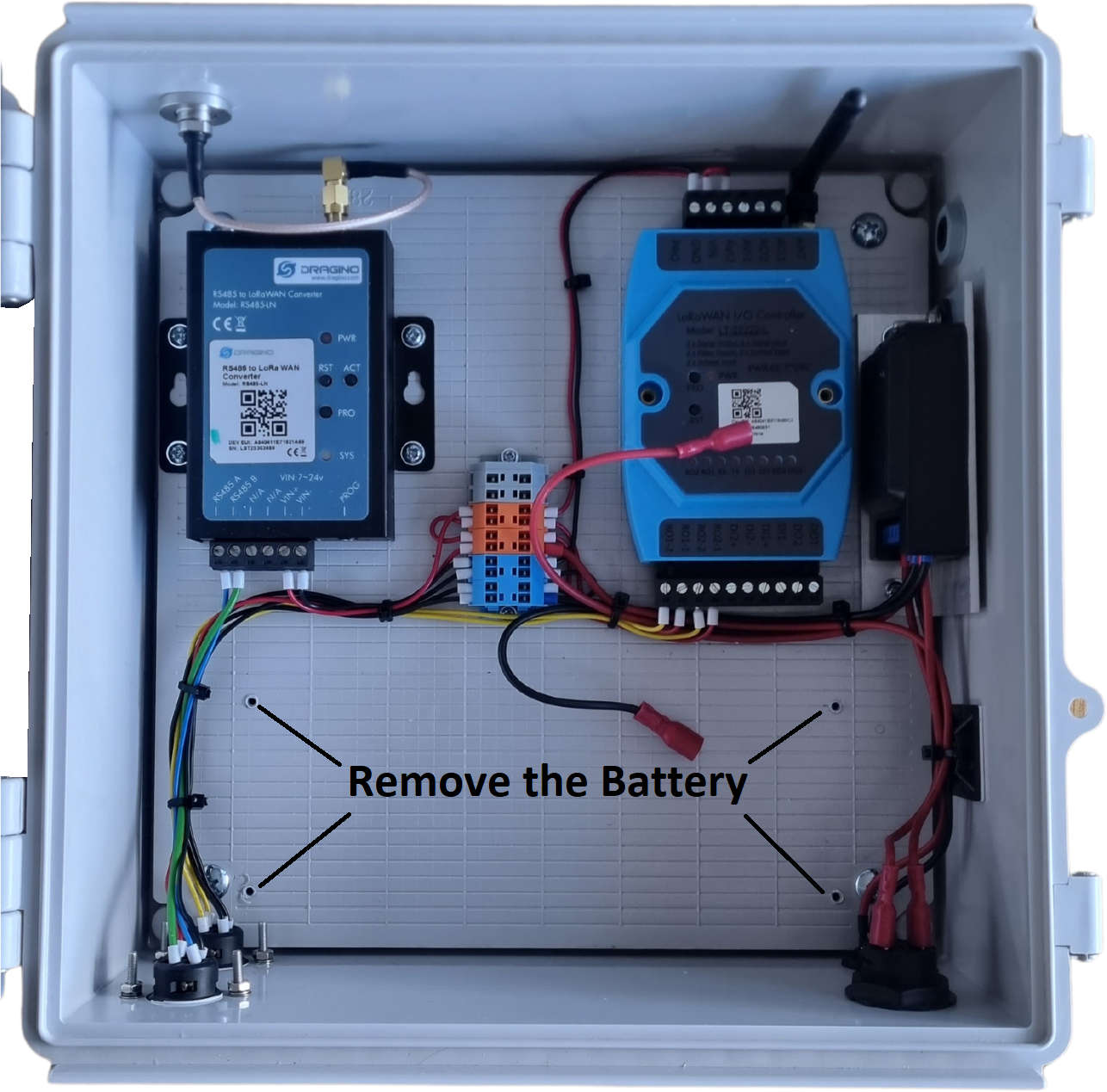
Remove the battery before handling the enclosure. This reduces the lifting weight and prevents the battery moving while the enclosure is placed face down.
- Set the external power switch to the off position.
- Undo the four Phillips-head screws and open the enclosure lid.
- Disconnect the battery leads and remove the battery if it has been installed for testing.
- Close the lid, secure it temporarily and place the enclosure face down on a clean, stable surface.
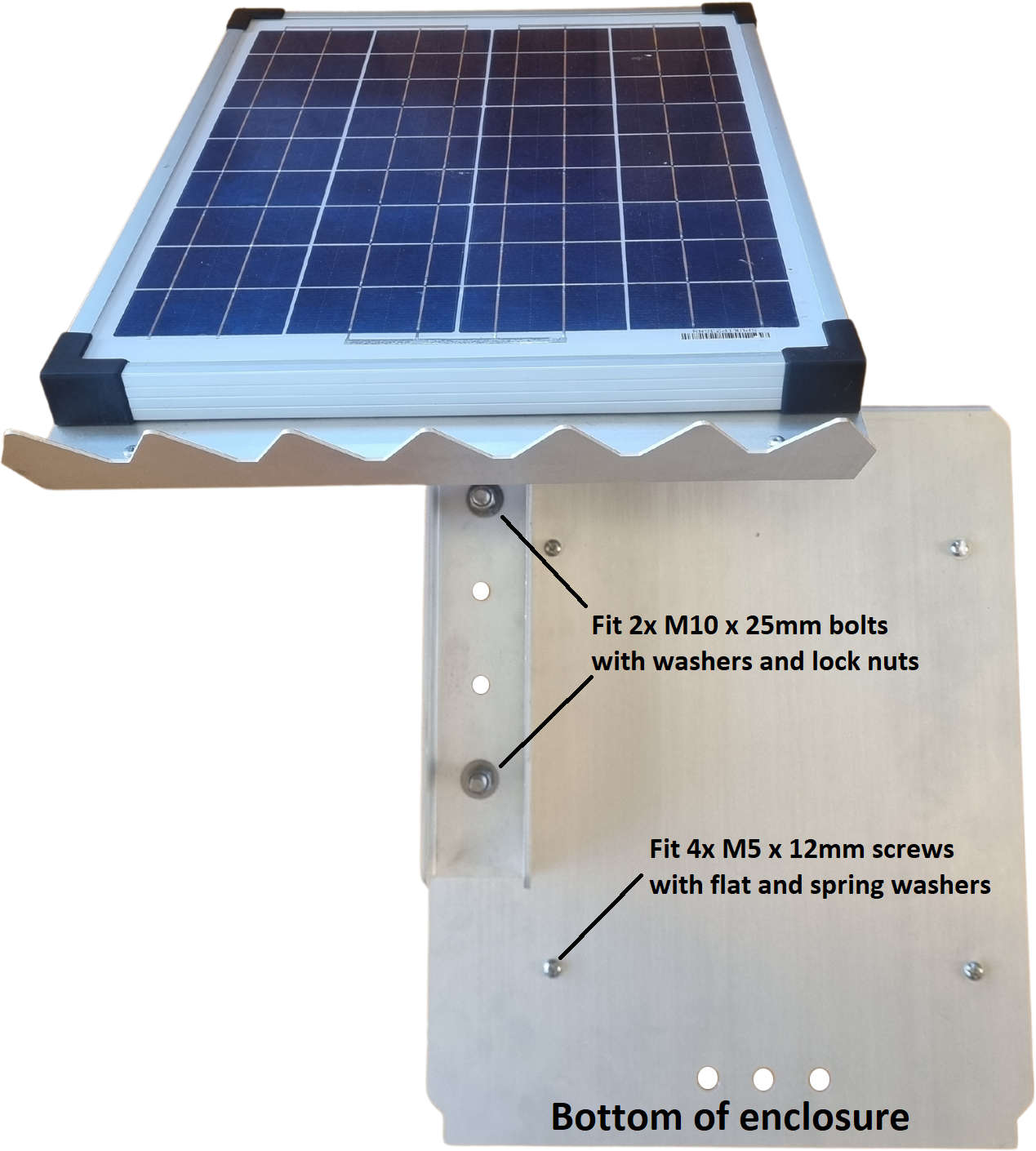
- Position the mounting plate against the back of the enclosure with the folded edges facing down, the solar-panel mounting holes at the top and the external connectors at the bottom.
- Secure the plate using the five supplied M5 × 12 mm pan-head screws, with one spring washer and one flat washer on each screw.
2. Attach the Solar Panel to the Mounting Plate
Use the lowest practical mounting position for a stable assembly while retaining enough clearance to open and service the enclosure.
- Loosen the solar-panel clamping bolts until the support arm can move freely.
- Position the solar-panel arm over the mounting holes in the backing plate.
- Use the panel assembly to assist with alignment, taking care not to trap or strain the solar cable.
- Install the two M10 × 25 mm bolts at the highest and lowest available fixing points.
- Fit a flat washer on each side and secure each bolt with the supplied lock nut.
- Tighten the mounting bolts with the 16 mm socket and ring spanner. Leave the panel clamping bolts adjustable until the final tilt is set.
3. Secure the Assembly to the Post
Mount the assembly high enough to protect the enclosure and provide clear solar exposure, while retaining safe access for battery and sensor maintenance.
- Lift the assembly into position with the external enclosure connectors facing down.
- For a standard 50 mm galvanised signpost with an approximately 60.5 mm outside diameter, secure the pre-fitted channels using the two supplied P2041 post brackets.
- For a suitable timber post, secure the backing plate using the two supplied M12 × 100 mm coach screws.
- Check that the backing plate is vertical and that all post fasteners are evenly tightened.
- Move the solar panel through its adjustment range and confirm that it does not contact the post, enclosure, antenna or cables.
Before continuing: Confirm that the post is stable, the assembly cannot rotate and the enclosure lid can still be opened safely for service access.
4. Install the Battery and Connect the Hardware
Keep the system switched off while installing the battery and connecting the solar panel and sensors. Connect the battery with the correct polarity before switching the system on.
- Confirm that the external power switch remains off.
- Tilt the solar panel temporarily if additional access to the enclosure is required.
- Open the enclosure and reinstall the 12 V 7 Ah battery in its bracket.
- Connect the red lead to the positive battery terminal and the black lead to the negative terminal.
- Secure the battery and place the supplied silica pack inside the enclosure where it cannot interfere with wiring or ventilation.
- Connect the solar-panel cable to its matching connector on the bottom of the enclosure.
- Connect the configured sensor or sensors to the labelled external ports.
- Check that all internal and external connectors are fully seated, then close and latch the enclosure.
- Press the external switch and confirm LED activity on the solar controller and installed wireless interface.
- Allow several minutes for the LoRaWAN or cellular connection to establish.
- Open Telemetry2U Reports and confirm that the expected node has received a current reading and timestamp.
Polarity warning: Do not reverse the battery leads. If the controller or wireless interface does not start, switch the system off and check the fuse, battery voltage, connector seating and configured communications hardware.
Battery Installation
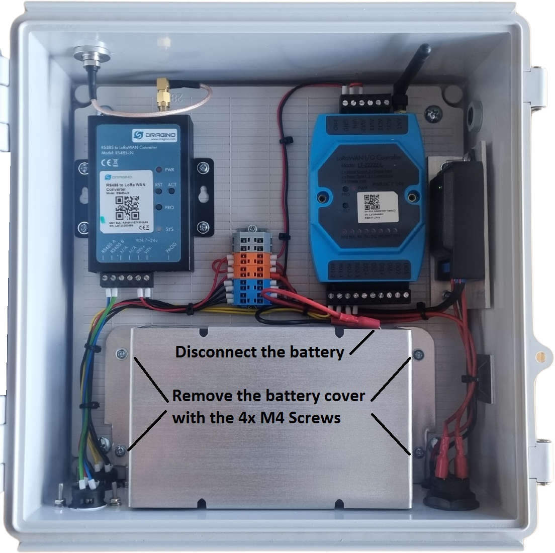
Keep the battery restrained so it cannot move against the controller, wiring or enclosure lid.
External Connections
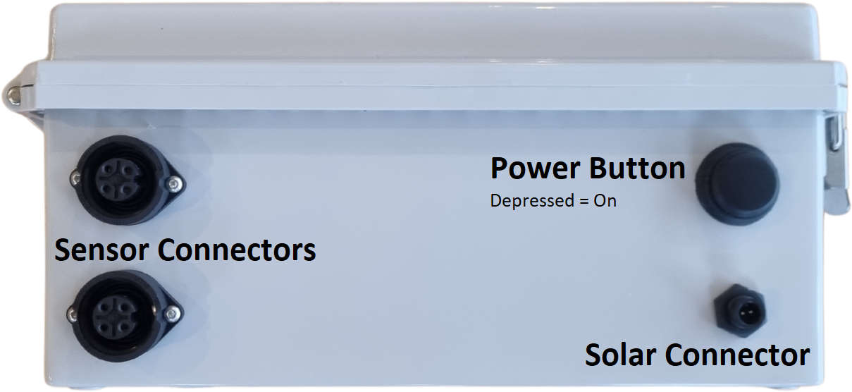
Route cables with a downward drip loop and avoid placing mechanical strain on the enclosure connectors.
5. Set the Solar-Panel Angle and Complete the Checks
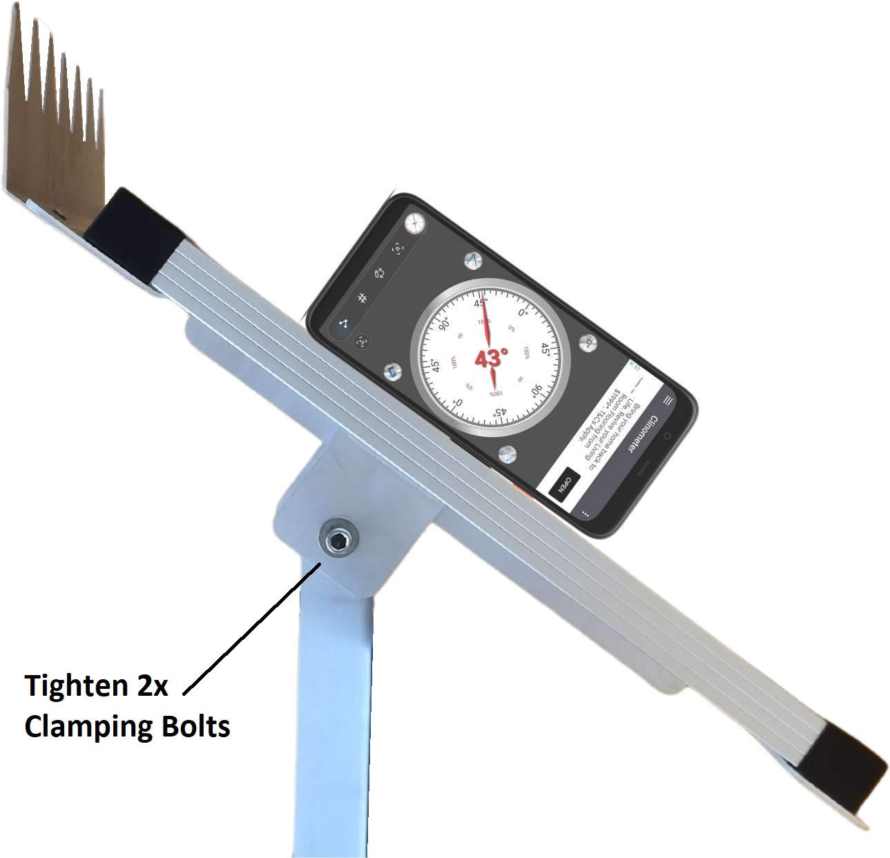
Aim the panel toward the equator and use the local latitude as a practical starting tilt angle. In southern Tasmania, an initial angle of approximately 43° is suitable before accounting for seasonal conditions and site shading.
- Confirm that the enclosure is fully closed and latched.
- Point the panel generally north in the Southern Hemisphere or south in the Northern Hemisphere.
- Measure the panel angle with an inclinometer, angle finder or smartphone app.
- Adjust the panel to the required tilt while checking that the cable remains free and unstressed.
- Tighten both clamping bolts securely with the 16 mm socket and ring spanner.
- Check that the panel is clear of nearby shading, vegetation and structures.
- Recheck the post brackets, panel fasteners, enclosure latches, antenna and cable routing.
- Confirm one final current reading in Telemetry2U Reports before leaving the site.
Commissioning complete: Record the installation date, final panel angle and connected sensor details. Schedule periodic checks for shading, loose fasteners, damaged cables, enclosure seals and battery condition.