Custom Payload Decoder Examples for LoRaWAN and NB-IoT Devices
Use these worked examples to understand how raw hexadecimal payloads are mapped to readable values in Telemetry2U, then add reusable downlink commands for supported device configuration and control.
Before You Create a Custom Decoder
A reliable decoder begins with the manufacturer’s payload specification, a known sample uplink and the correct byte order. The examples below show the Telemetry2U workflow, but the installed firmware and current device manual remain the source of truth for field positions, ports and command syntax.
Use an active trial or paid account with access to the required company and nodes.
Your role must allow access to Custom Devices and Node Maintenance.
Obtain the current byte map, byte order, scaling, FPort and report-type details.
Use a captured uplink with independently known values before approving the decoder.
Important: These are worked examples rather than universal device profiles. Manufacturers can change payloads between firmware versions. Confirm every field and downlink command against the exact hardware and firmware being deployed.
Custom Device Workflow in Telemetry2U
Create the decoder first, validate it with known uplinks, then add only the downlink commands needed by authorised users.
- Open Admin > Custom Devices and select Create New.
- Enter the device name, FPort, byte order and expected field count.
- Add each payload field using its start byte, length, data type, scaling, offset and precision.
- Use Match Offset fields where fixed bytes identify a device, report type or operating mode.
- Save the decoder and assign it as the Device Configuration in Admin > Node Maintenance.
- Confirm the displayed values against a known payload before enabling alerts, reports or automation.
- Add required commands under Downlink Commands, then send them from Admin > Send Node Commands or an authorised dashboard button.
Worked Examples
Dragino LT22222L
MSB payload with analogue inputs, digital states, relay states and an operating-mode byte.
View Dragino exampleNetvox RB11E
MSB payload with fixed report identifiers, battery voltage, temperature, light and occupancy.
View Netvox exampleMilesight WS523
Little-endian channel-and-type payload containing socket state and electrical measurements.
View Milesight exampleDragino LT22222L I/O Controller
This example decodes the 11-byte AT+MOD=1 uplink. The Dragino manual
specifies FPort 2 and a payload containing two voltage inputs, two current inputs,
one combined digital/relay status byte, one reserved byte and one mode byte.
Example payload: 04AB04AC13101300AAFF01
| Channel | Start byte | Length | HEX | Data type | Raw value | Scaling | Result |
|---|---|---|---|---|---|---|---|
| Voltage 1 (AVI1) | 0 | 2 | 04 AB |
Unsigned integer | 1195 | ÷ 1000 | 1.195 V |
| Voltage 2 (AVI2) | 2 | 2 | 04 AC |
Unsigned integer | 1196 | ÷ 1000 | 1.196 V |
| Current 1 (ACI1) | 4 | 2 | 13 10 |
Unsigned integer | 4880 | ÷ 1000 | 4.880 mA |
| Current 2 (ACI2) | 6 | 2 | 13 00 |
Unsigned integer | 4864 | ÷ 1000 | 4.864 mA |
| Digital and relay status | 8 | 1 | AA |
Bit field | 170 | Binary | 10101010 |
| Reserved | 9 | 1 | FF |
Reserved | Skipped | — | — |
| Operating mode | 10 | 1 | 01 |
Match Offset | 1 | 1 | MOD1 |
Bytes 0–7 are interpreted as unsigned MSB values and divided by 1000. Byte 8 is decoded bit by bit. Byte 9 is skipped, while Byte 10 is configured as a Match Offset so that a MOD1 payload is not processed by a decoder intended for another operating mode.
| Channel | Bit | State | Meaning |
|---|---|---|---|
| Relay 1 | 7 | 1 | Closed |
| Relay 2 | 6 | 0 | Open |
| DI3 / unused on LT22222L | 5 | 1 | Ignore for LT22222L |
| Digital input 2 | 4 | 0 | Low |
| Digital input 1 | 3 | 1 | High or floating |
| DO3 / unused on LT22222L | 2 | 0 | Ignore for LT22222L |
| Digital output 2 | 1 | 1 | Low / on |
| Digital output 1 | 0 | 0 | High or floating / off |
Create a separate decoder for each supported operating mode and use the final mode byte as a Match Offset. Configure the next decoder in the chain so a payload that fails the mode match can continue to the correct profile.
Decoder configuration
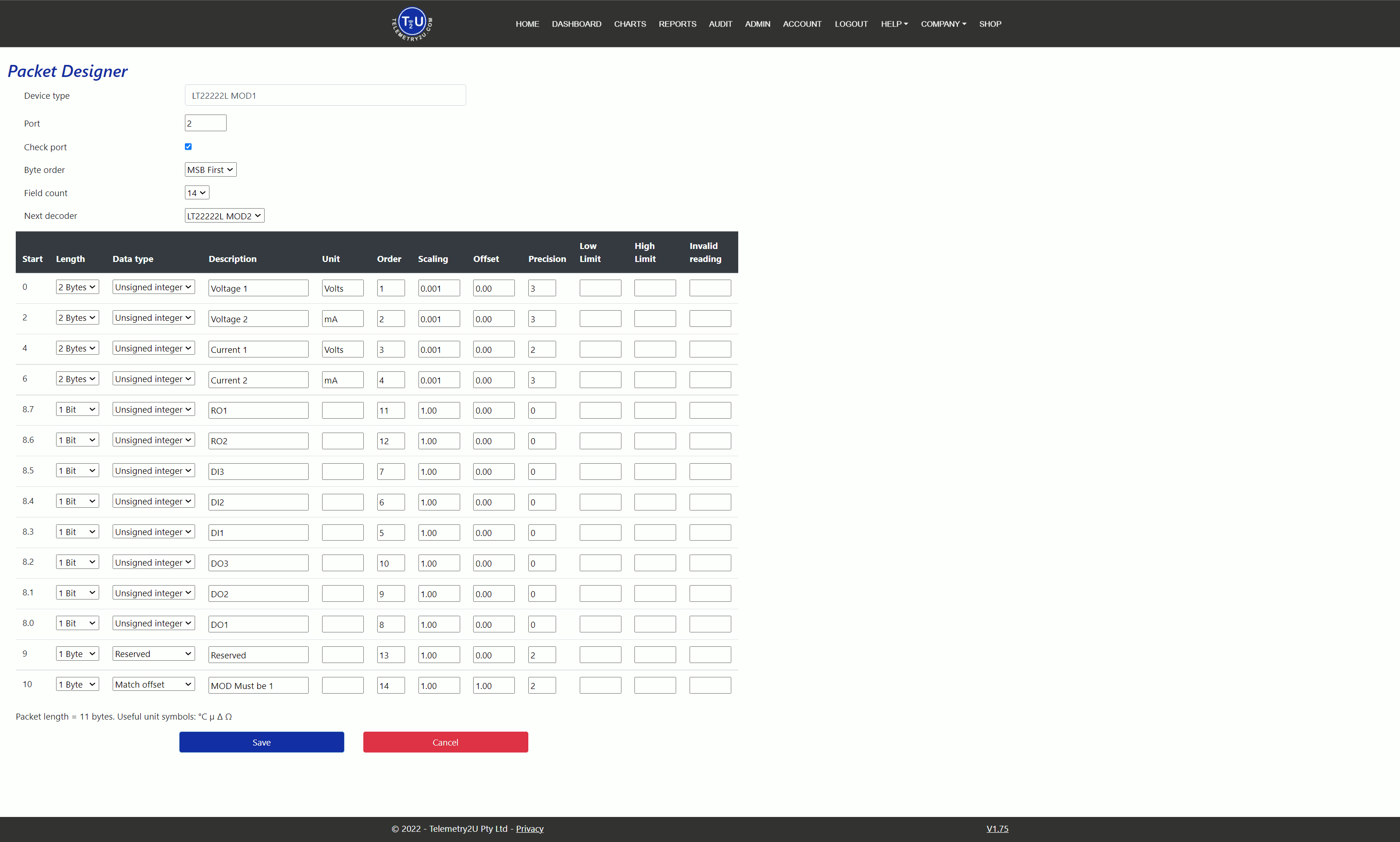
Select Save, assign the decoder to a test node and compare every result with the known payload.
Downlink commands
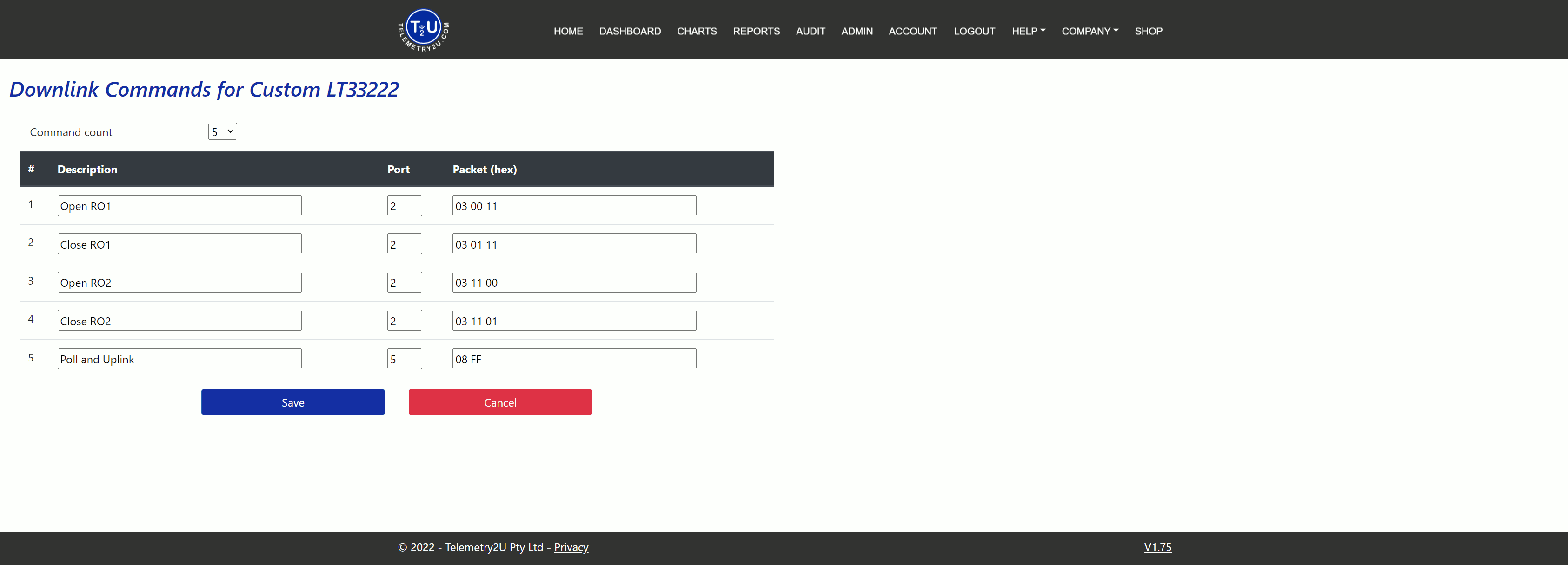
Use the current Dragino command specification for the installed firmware before reusing any hexadecimal command.
Netvox RB11E Occupancy Sensor
The RB11E combines temperature, illuminance, passive infrared occupancy and a tamper input. This example uses an 11-byte MSB uplink received on FPort 6.
Example payload: 010301240B1C007B010000
| Channel | Start byte | Length | HEX | Data type | Raw value | Scaling | Result |
|---|---|---|---|---|---|---|---|
| Version | 0 | 1 | 01 | Match Offset | 1 | 1 | 1 |
| Device type | 1 | 1 | 03 | Match Offset | 3 | 1 | RB11E |
| Report type | 2 | 1 | 01 | Match Offset | 1 | 1 | Sensor report |
| Battery | 3 | 1 | 24 | Unsigned integer | 36 | ÷ 10 | 3.6 V |
| Temperature | 4 | 2 | 0B 1C | Integer per device profile | 2844 | ÷ 100 | 28.44 °C |
| Illuminance | 6 | 2 | 00 7B | Unsigned integer | 123 | 1 | 123 lux |
| Occupancy | 8 | 1 | 01 | Unsigned integer | 1 | 1 | Occupied |
| Tamper | 9 | 1 | 00 | Unsigned integer | 0 | 1 | Assembled |
| Reserved | 10 | 1 | 00 | Reserved | Skipped | — | — |
Configure the first three bytes as Match Offset fields. This prevents a different Netvox report type from being decoded with the sensor-report layout. Battery, temperature and illuminance then use their documented scaling, while occupancy and tamper are binary state fields.
Netvox documents configuration requests on FPort 7, while the example sensor uplink is received on FPort 6. Confirm both ports and the signed-temperature behaviour against the installed firmware before creating a production command profile.
RB11E Downlink Examples
A configuration command can combine the minimum reporting interval, maximum reporting interval, battery-change threshold, temperature-change threshold and illuminance-change threshold. Separate commands can set the PIR disable and detection periods.
Decoder configuration
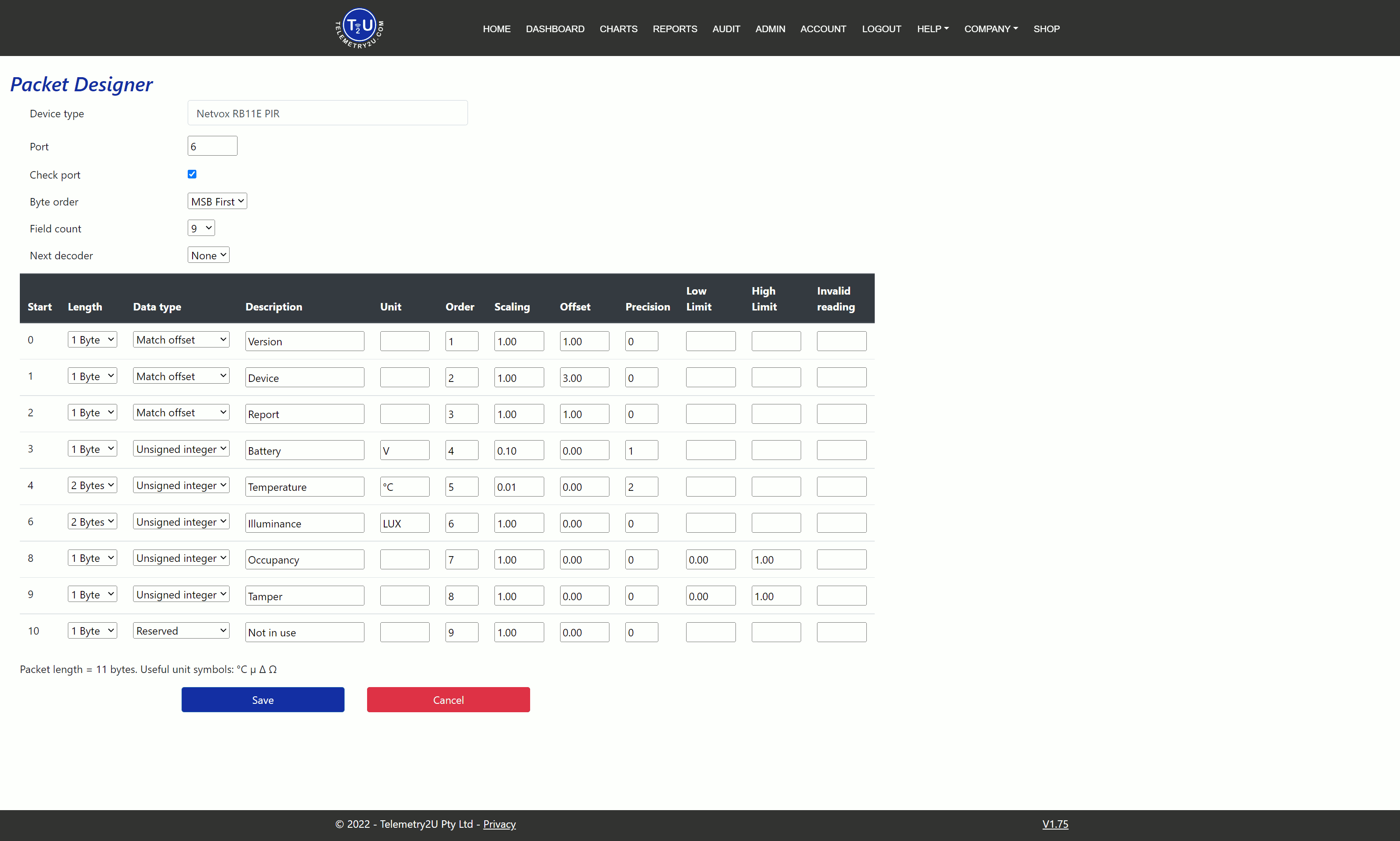
Validate occupied, unoccupied and tamper states, as well as a known temperature and light reading.
Downlink commands
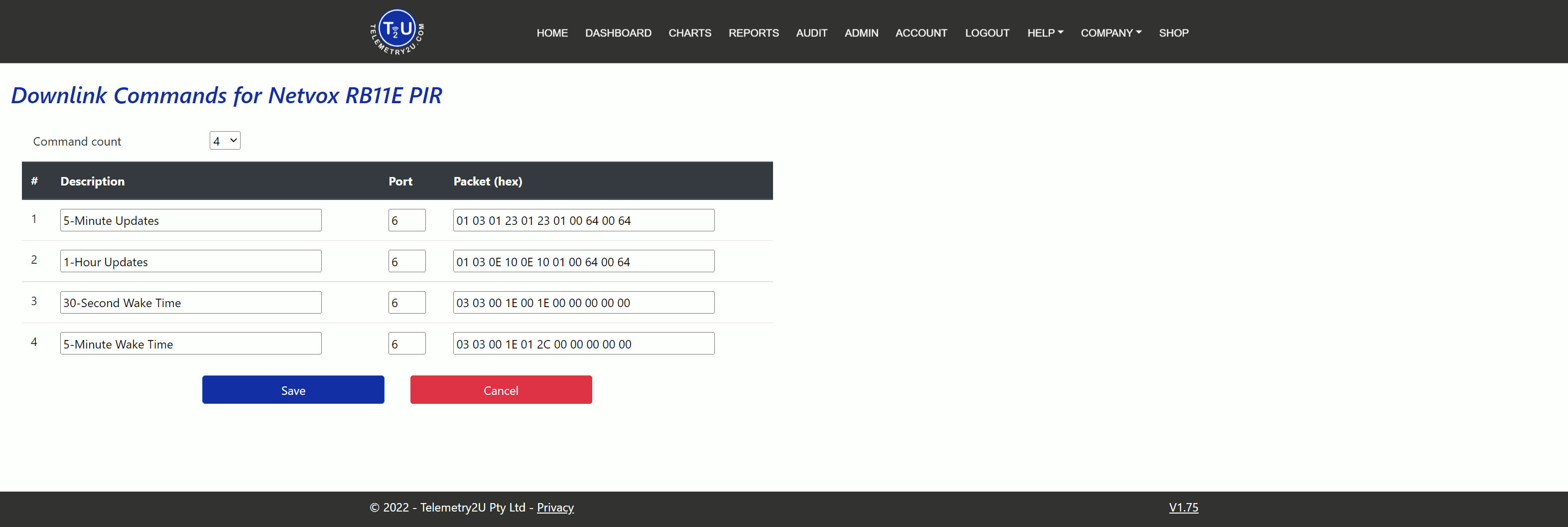
Keep the minimum interval practical for battery life and ensure the PIR detection period is not shorter than the disable period.
Milesight WS523 Smart Socket
The WS523 reports a sequence of channel, type and data fields on FPort 85. Data
values use little-endian byte order. The first 08 70 channel/type pair
can be used as a Match Offset to identify the periodic electrical report.
Example payload: 08700105816307C99D0D03743A090683D4360000048038030000
| Channel | Start byte | Length | HEX | Data type | Raw value | Scaling | Result |
|---|---|---|---|---|---|---|---|
| Channel / type | 0 | 2 | 08 70 | Match Offset | 28680 | 1 | Socket status field |
| Socket status | 2 | 1 | 01 | Unsigned integer | 1 | 1 | Open / on |
| Channel / type | 3 | 2 | 05 81 | Reserved | Skipped | — | Power factor follows |
| Power factor | 5 | 1 | 63 | Unsigned integer | 99 | 1 | 99% |
| Channel / type | 6 | 2 | 07 C9 | Reserved | Skipped | — | Current follows |
| Current | 8 | 2 | 9D 0D | Unsigned integer | 3485 | ÷ 1000 | 3.485 A |
| Channel / type | 10 | 2 | 03 74 | Reserved | Skipped | — | Voltage follows |
| Voltage | 12 | 2 | 3A 09 | Unsigned integer | 2362 | ÷ 10 | 236.2 V |
| Channel / type | 14 | 2 | 06 83 | Reserved | Skipped | — | Consumption follows |
| Consumption | 16 | 4 | D4 36 00 00 | Unsigned integer | 14036 | ÷ 1000 | 14.036 kWh |
| Channel / type | 20 | 2 | 04 80 | Reserved | Skipped | — | Active power follows |
| Active power | 22 | 4 | 38 03 00 00 | Unsigned integer | 824 | 1 | 824 W |
The first pair is interpreted in little-endian order, so 08 70 becomes
0x7008, or 28680 decimal. The remaining channel/type pairs are skipped as
reserved fields and each following data value uses its documented length and scaling.
In periodic reports, socket status 00 means closed/off and
01 means open/on. Socket-change reports can also use 10
for closed by the local button and 11 for opened by the local button.
WS523 Downlink Examples
Useful commands can include socket on, socket off, button-lock control and a delayed
switching task. Multi-byte values must be entered in the byte order required by the
Milesight protocol. For example, 3600 seconds is hexadecimal 0x0E10 and
is transmitted as little-endian bytes 10 0E within the task payload.
Decoder configuration
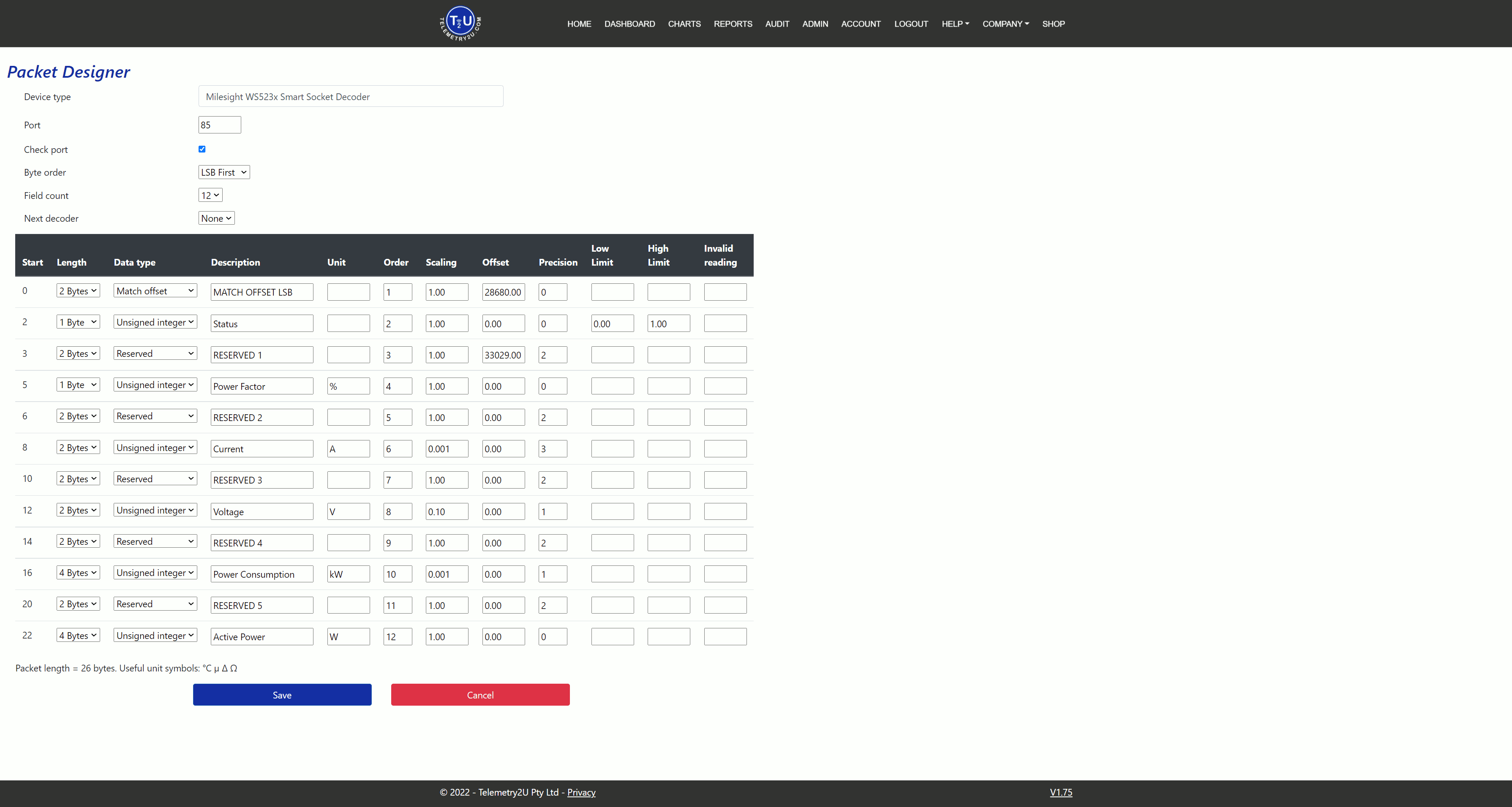
Test the decoder with the socket both on and off, then compare voltage, current, power and consumption with known values.
Downlink commands
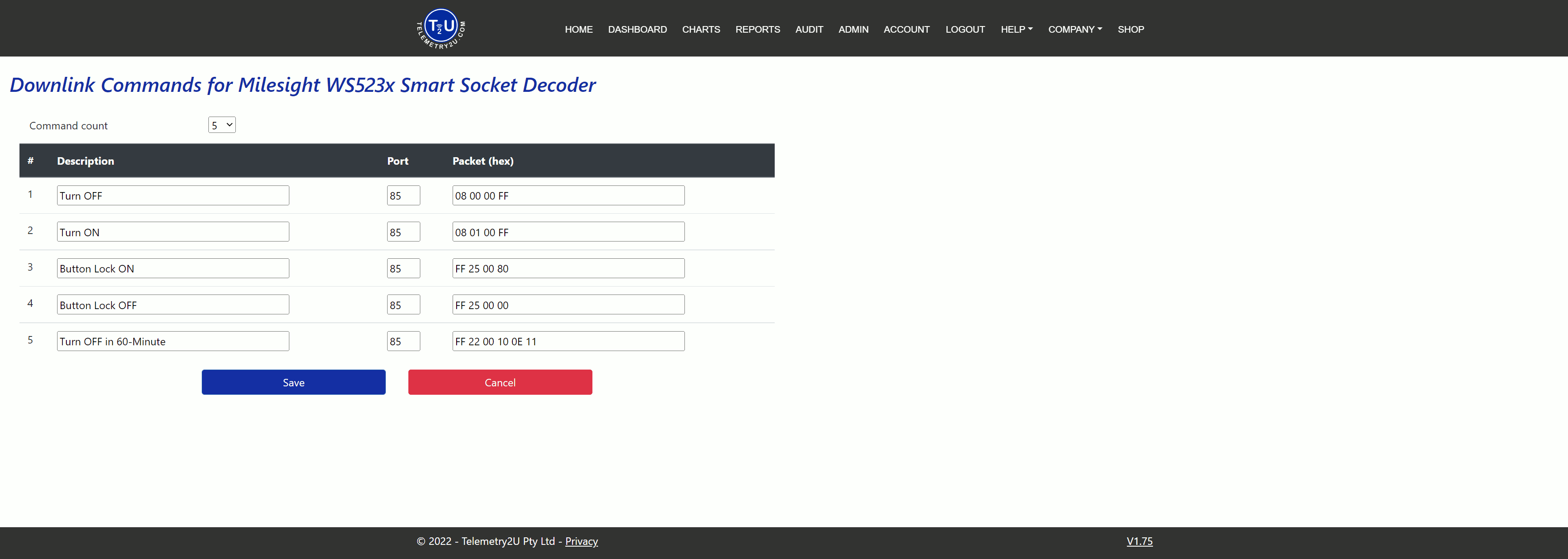
Confirm electrical ratings, device state and local safety requirements before enabling remote control.