Configure a Dragino LoRaWAN Gateway for Telemetry2U
Access a Dragino gateway, connect it to the Internet, confirm the regional LoRa settings and forward packets to the correct Telemetry2U LoRaWAN server.
Before You Change the Gateway Network Configuration
LoRaWAN gateways supplied by Telemetry2U are normally tested and configured before dispatch. In most installations, connect power and Ethernet and allow the gateway to obtain an address from the local router.
Use this guide when commissioning a replacement gateway, restoring settings or diagnosing a connection fault. The screenshots use a Dragino LG308. Menu names can vary between gateway models and firmware releases, but the main settings are similar across many Dragino Linux gateways.
For model-specific details, use the official Dragino documentation for the LPS8, LG308 or DLOS8.
Use a computer or phone connected to the gateway or the same local network.
New gateways commonly use admin and dragino until the password is changed.
Confirm the required LoRaWAN region and sub-band before changing the radio configuration.
Keep the assigned email address and Gateway ID supplied for this gateway.
Do not change a working gateway unnecessarily. Incorrect radio, server or identity settings can prevent all connected sensors from reporting.
1. Access the Dragino Gateway
Use the access method available at the installation. After opening the gateway interface, sign in with the current administration credentials.
Wi-Fi Access Point
Connect to dragino-xxxxxx. Current Dragino firmware
commonly uses the access-point password dragino+dragino.
Open http://10.130.1.1.
WAN or Router
Find the DHCP address assigned to the gateway in the router client
list, then open that address on port 8000, for example
http://192.168.1.100:8000.
Direct LAN Port
On models with a LAN port, connect a computer with DHCP enabled and
open http://10.130.1.1. Confirm the port function in the
manual for the installed model.
The default web-interface username is commonly admin with password
dragino. Use the current credentials if the password has already
been changed.

For phone-based first-time setup, follow Configure a LoRaWAN Gateway via Wi-Fi.
2. Check Gateway Status and Change the Password
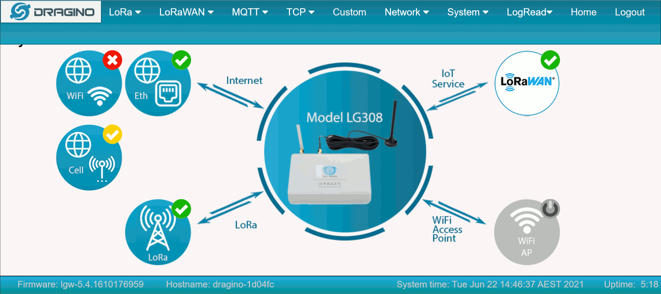
The Dragino home screen summarises the radio, Internet and network-server connections. Read the text label with the status colour rather than relying on colour alone.
The connection or service is operating and currently selected.
The interface is available but may not be the active route.
The connection or service is unavailable and requires attention.
Replace the Default Administration Password
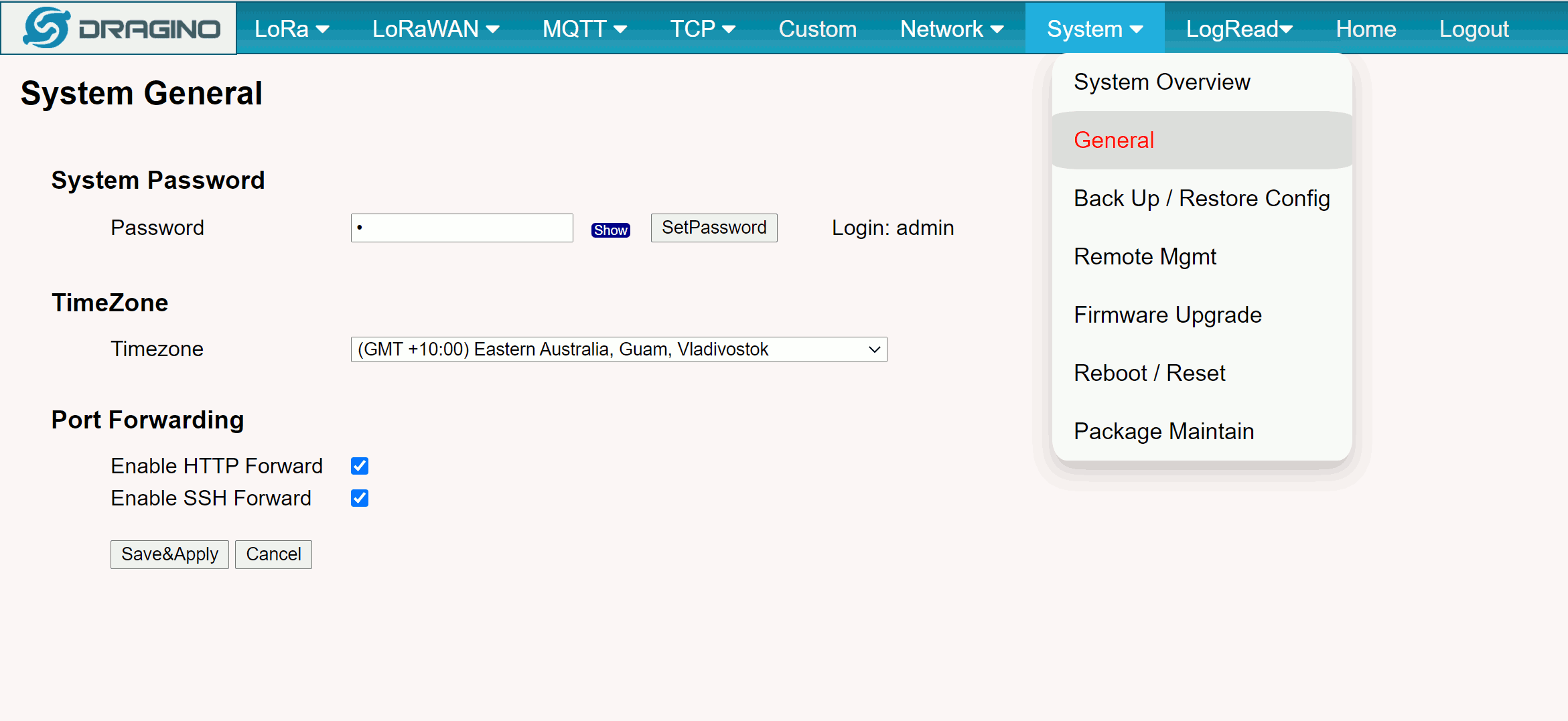
Open System > General, enter a new password, select SetPassword, then select Save & Apply. Use a unique password stored with the site or customer commissioning record.
3. Configure Wi-Fi Internet Access
Skip this section when the gateway will remain connected by Ethernet or cellular. To use an existing wireless network, open Network > WiFi and enable the Wi-Fi WAN client.
- Enable WiFi WAN Client Settings.
- Enter the host network name in Host WiFi SSID.
- Enter the wireless-network password in Passphrase.
- Select the encryption method used by the host access point.
- Select Save & Apply, then confirm that the Wi-Fi WAN status succeeds.
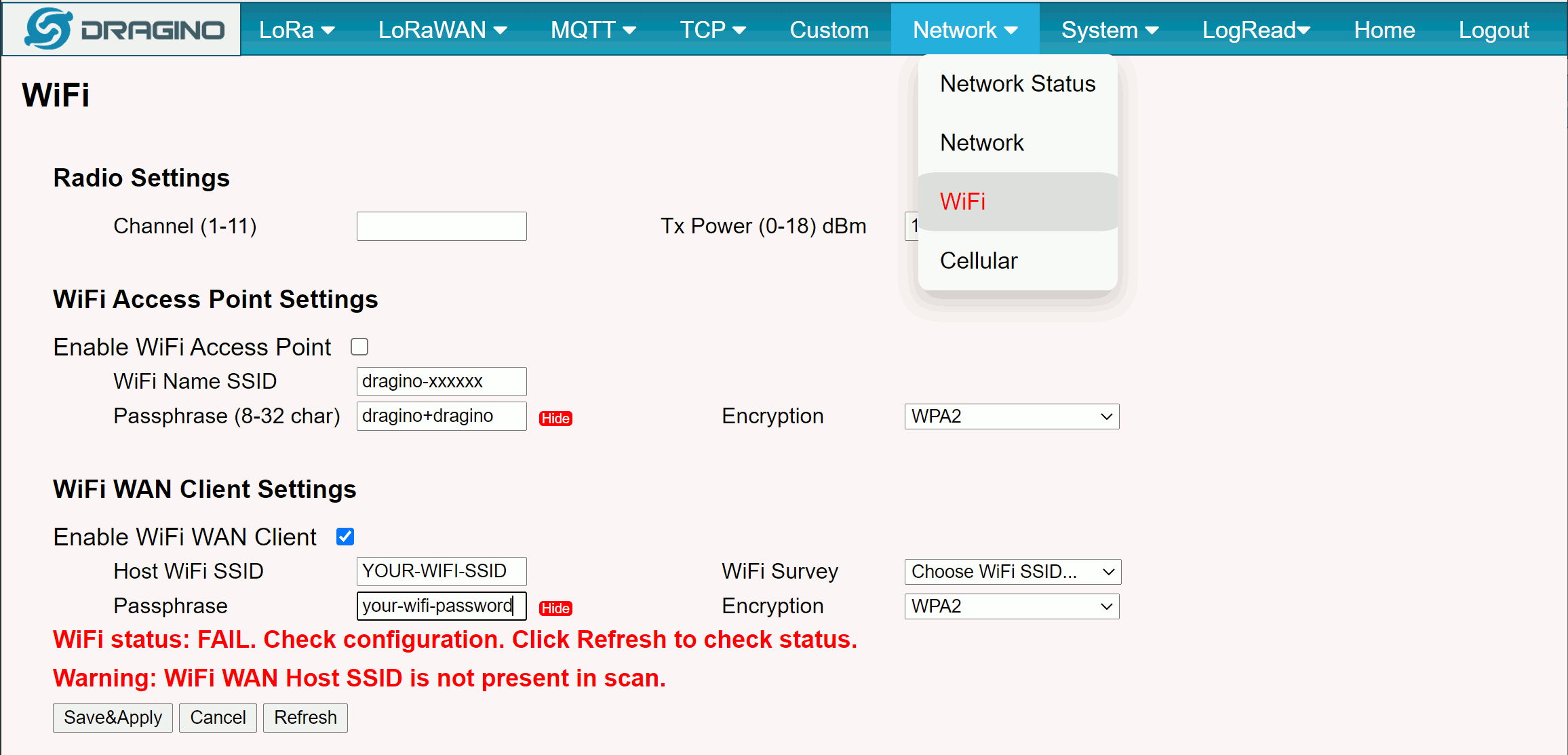
Keep the gateway access point enabled until the new WAN connection has been tested. Disabling the access point too early can make local recovery more difficult.
4. Confirm the LoRa Radio Settings
Open LoRa > LoRa and confirm that the frequency plan matches the sensors and the Telemetry2U network assigned to the gateway.
Australian Telemetry2U deployments normally use AU915. The example below uses Sub-band 2, covering uplink channels 8–15 from 916.8 to 918.2 MHz. Use the exact regional plan and sub-band specified for the installation.
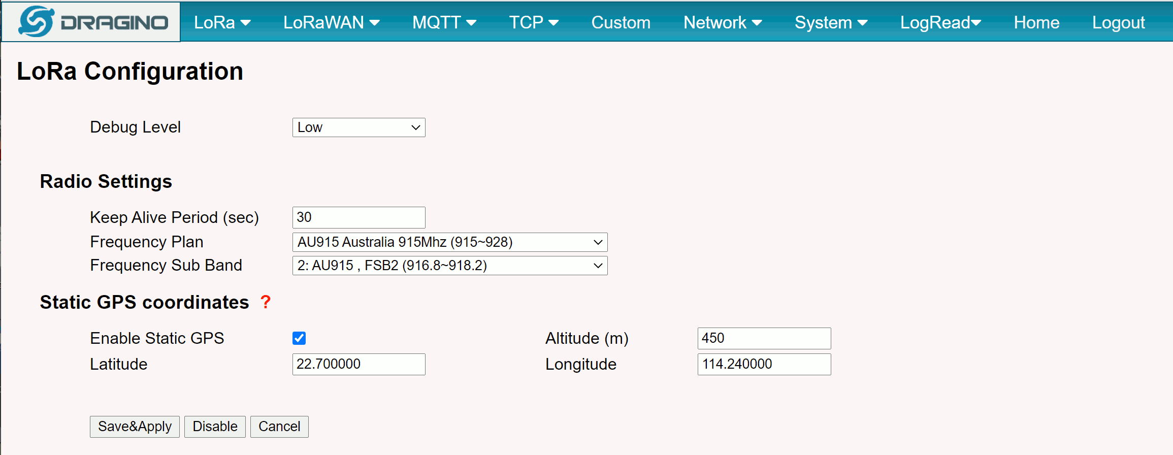
Static GPS coordinates are optional on gateways without an integrated GPS receiver and are not required for normal packet forwarding. If the LoRa service is not operating, the home-screen LoRa indicator will show a failed state.
5. Configure the Telemetry2U LoRaWAN Server
Open LoRaWAN > LoRaWAN, select Custom / Private LoRaWAN and enter the server address and UDP port for the gateway frequency plan.
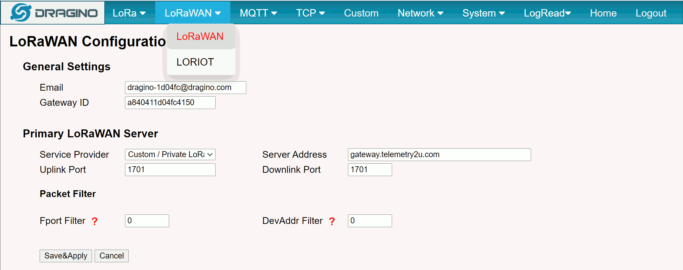
Select a server address or port below to copy it to the clipboard.
| Frequency Plan | Server Address | UDP Uplink / Downlink Port |
|---|---|---|
| AS923 | ||
| AS923-2 | ||
| AS923-3 | ||
| AS923-4 | ||
| AU915 | ||
| CN470 | ||
| CN779 | ||
| EU433 | ||
| EU868 | ||
| IN865 | ||
| KR920 | ||
| RU864 | ||
| US915 |
Preserve the gateway identity. The Email and Gateway ID
values identify the gateway in Telemetry2U and must match the registered
record. Set both packet-filter values to 0 unless Telemetry2U
support has provided different instructions.
6. Allow Network Traffic and Verify the Connection
Most routers allow the required outbound traffic without manual changes. On a restricted corporate, healthcare or laboratory network, provide the following requirements to the network administrator.
Telemetry2U Packet Forwarding
Allow outbound UDP from the gateway to the selected Telemetry2U server and regional port. Permit the corresponding return traffic to the gateway's temporary source port.
Network Time Protocol
Allow outbound and return UDP traffic on port 123 so the
gateway can synchronise its clock with an available NTP service.
Connectivity Checks
If gateway Internet tests rely on ICMP, allow echo requests and replies to the configured test addresses. A blocked ping does not always mean packet forwarding is unavailable.
MAC Address Allowlisting
When MAC filtering is enabled, use the address displayed for the active Ethernet, Wi-Fi or cellular interface on the label or Network Status page. Verify the value rather than calculating it.
Final Connection Check
- Select Save & Apply after any configuration change.
- Return to the gateway home screen after the services restart.
- Confirm that the LoRa indicator is active.
- Confirm that the IoT Service indicator is active.
- Confirm that at least one Internet interface is active.
- Check Telemetry2U for new sensor packets or ask support to confirm gateway traffic.
If LoRa is active but IoT Service remains failed, recheck the regional server, UDP port, Email, Gateway ID and packet filters. If all Internet interfaces fail, resolve the local network connection or firewall rules first.