How to Install Temperature Sensors in Fridges and Freezers
Install a wireless temperature-monitoring sensor with an aluminium buffer and door-seal cable guide, then confirm that reliable readings are reaching the Telemetry2U platform.
Prepare the Installation Before Opening the Fridge or Freezer
Telemetry2U hardware supplied in plug-and-play format is normally configured and attached to the correct account before delivery. Complete the network and device checks first so the fridge or freezer only needs to remain open for the physical installation.
Confirm that the probe, node, antenna and batteries or power supply are ready.
Use a connected LoRaWAN gateway or a supported NB-IoT or LTE-M service.
Prepare the aluminium buffer, cable ties, adhesive mounts and cable seal.
Sign in to the account that contains the gateway, node and temperature input.
Plan the cable route before starting. Use an existing cable-entry port where available. When the probe must pass through the door seal, keep the cable straight and level at the crossing point so it is not pinched or sharply bent.
1. Power the Gateway and Temperature Sensor
Confirm that the monitoring hardware is online before fitting the probe inside the cold-storage unit. Cellular nodes connect directly to the mobile network; LoRaWAN nodes also require an operating gateway.
LoRaWAN Gateway
- Attach the gateway antennas before applying power.
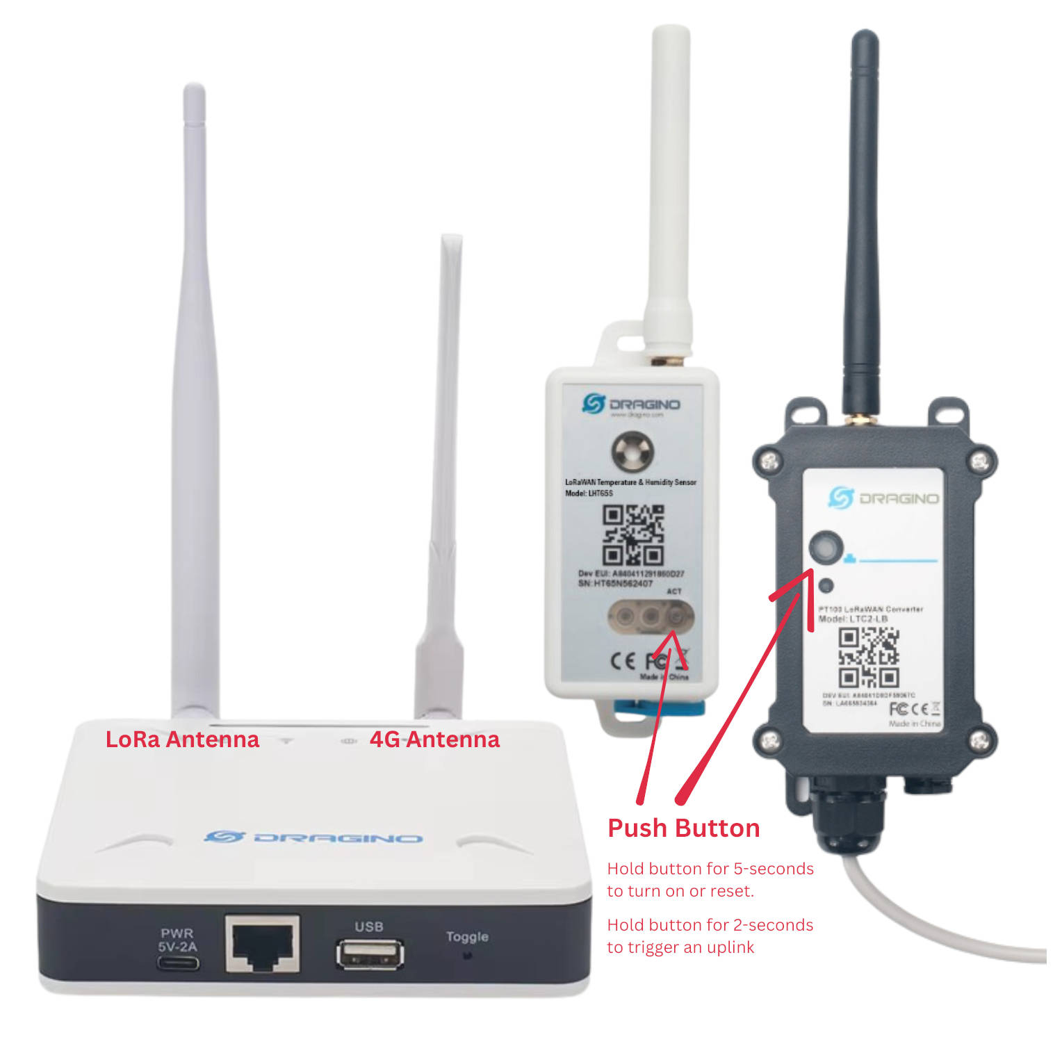
- If two antennas are supplied, connect the round antenna to the LoRa port and the flat antenna to the 4G port.
- Connect the gateway to Ethernet, configured Wi-Fi or its supplied cellular service.
- After the gateway has started, confirm its recent connection time under Gateways and Networks > View Gateway Status.
Temperature Sensor Node
- Attach the antenna where the node uses an external antenna.
- Hold the node button for approximately five seconds to turn it on or reset it. The LED should begin flashing after release.
- Check the relevant Telemetry2U report or device page to confirm that the node is sending data.
A gateway that still requires Wi-Fi configuration can be set up using the Dragino gateway Wi-Fi configuration guide.
2. Install the Aluminium Temperature Buffer
The aluminium buffer slows the probe response to brief air-temperature changes caused by door openings and defrost cycles. This produces a reading that more closely represents the temperature of the stored products.
- Choose a fixed position close to the products being monitored.
- Prefer the central area beneath the middle shelf where practical.
- Avoid the cabinet walls, top shelf, evaporator coil and defrost element.
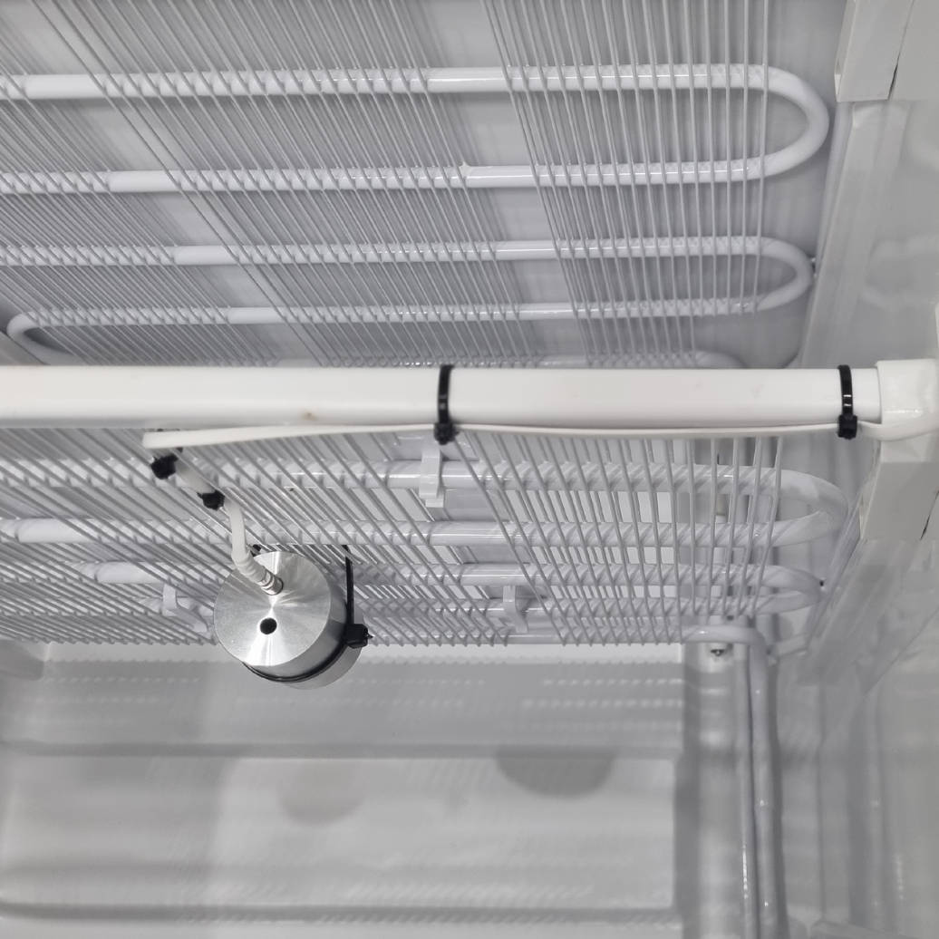
- Secure the buffer firmly to the shelf with cable ties so it cannot move during normal use.
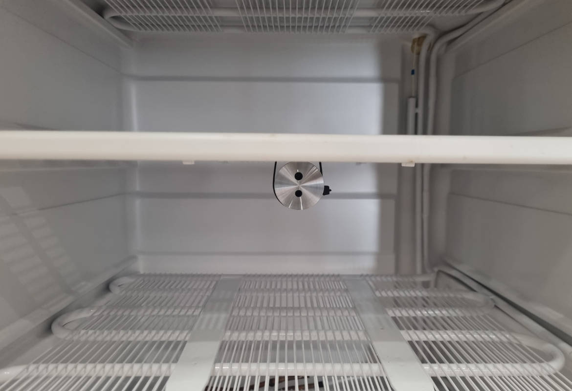
Telemetry2U aluminium buffers are designed to approximate the thermal response of 30 mL of water without using a liquid-filled bottle. Additional thermowells can also hold a reference probe during calibration or verification work.
3. Insert the Probe and Route the Sensor Cable
Keep the probe fixed in the buffer and support the cable so normal shelf movement, loading and cleaning cannot pull it free.
- Insert the temperature probe into the thermowell that provides the best fit.
- Secure the probe cable to the shelf wire close to the buffer, leaving slight slack to avoid strain.
- Continue securing the cable along the shelf toward the selected exit point.
- Use the fridge or freezer cable-entry port when one is available.
- When routing through the door seal, keep the cable straight and level where the door closes.
4. Fit the Cable Seal and Mount the Wireless Node
Complete the installation outside the cabinet by protecting the door-seal crossing, supporting the external cable and positioning the wireless node for reliable radio communication.
Fit the Cable Seal
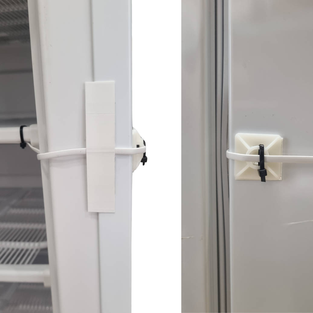
- Position the seal over the probe cable where the door closes and mark its location.
- Remove the adhesive backing and press the seal firmly onto the cabinet face.
- Route the cable around the cabinet edge without a sharp bend.
- Fit an adhesive cable-tie mount close to the edge and secure the cable.
Mount the Sensor Node
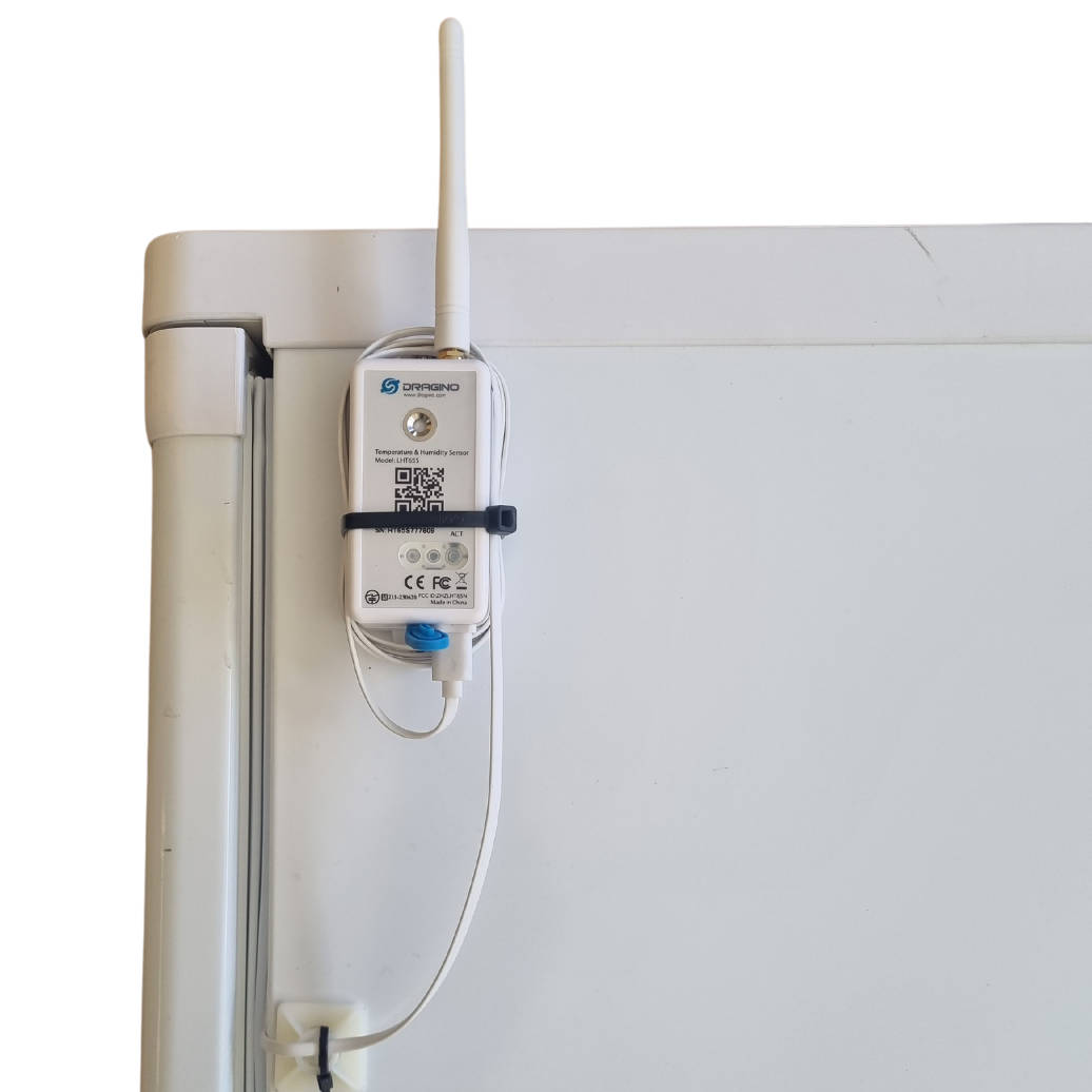
- Connect the probe to the wireless node where it uses a detachable connector.
- Mount the node high on the outside of the cabinet using its magnets or suitable mounting hardware.
- Position an external antenna above the cabinet to reduce obstruction by the metal enclosure.
- Secure excess cable neatly without tight coils, sharp bends or strain on the connector.
5. Verify the Installation and Allow the Reading to Stabilise
Confirm the radio connection immediately, then allow the buffer and probe to reach the cabinet temperature before judging the final reading.
- Close the fridge or freezer and check that the door seal sits evenly around the cable guide.
- Press the node button for approximately two seconds to trigger an uplink.
- Sign in to Telemetry2U and confirm that a new temperature reading has been received.
- Check that the probe cable, node and antenna remain secure and do not interfere with normal use.
- Allow up to one hour for the buffered reading to stabilise, particularly when the door was open during installation.
Do not adjust alert thresholds or assume the installation is faulty while the buffer is still cooling or warming to the cabinet temperature. Review the trend after the reading has settled.
Optional: Record the Fridge or Freezer Details
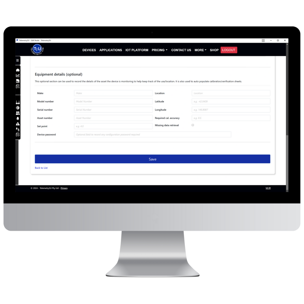
Equipment details can be stored against the monitored device so the make, model, serial number, asset number, location and required calibration accuracy are available for maintenance and calibration records.
- Open Nodes Maintenance > Add / Edit Nodes and Devices.
- Select Edit beside the relevant device.
- Complete the Optional – Equipment Details fields and select Save.